



Custom Mold Limit Pin Drawing Checklist for Supplier RFQs
A custom mold limit pin drawing must define more than the pin’s basic diameter and length. For a supplier to prepare a reliable quotation, the package should also identify the pin’s function, mating components, fit, material, heat treatment, surface requirements, inspection scope, quantity, and delivery conditions.
This guide applies after you have determined that a catalog component cannot meet the required geometry, fit, material, or operating conditions. For broader guidance on that decision, see mold standard parts (inferred).
The goal is not to make every drawing complex. It is to give the supplier enough controlled information to quote the same part you intend to purchase, without filling critical gaps with assumptions.
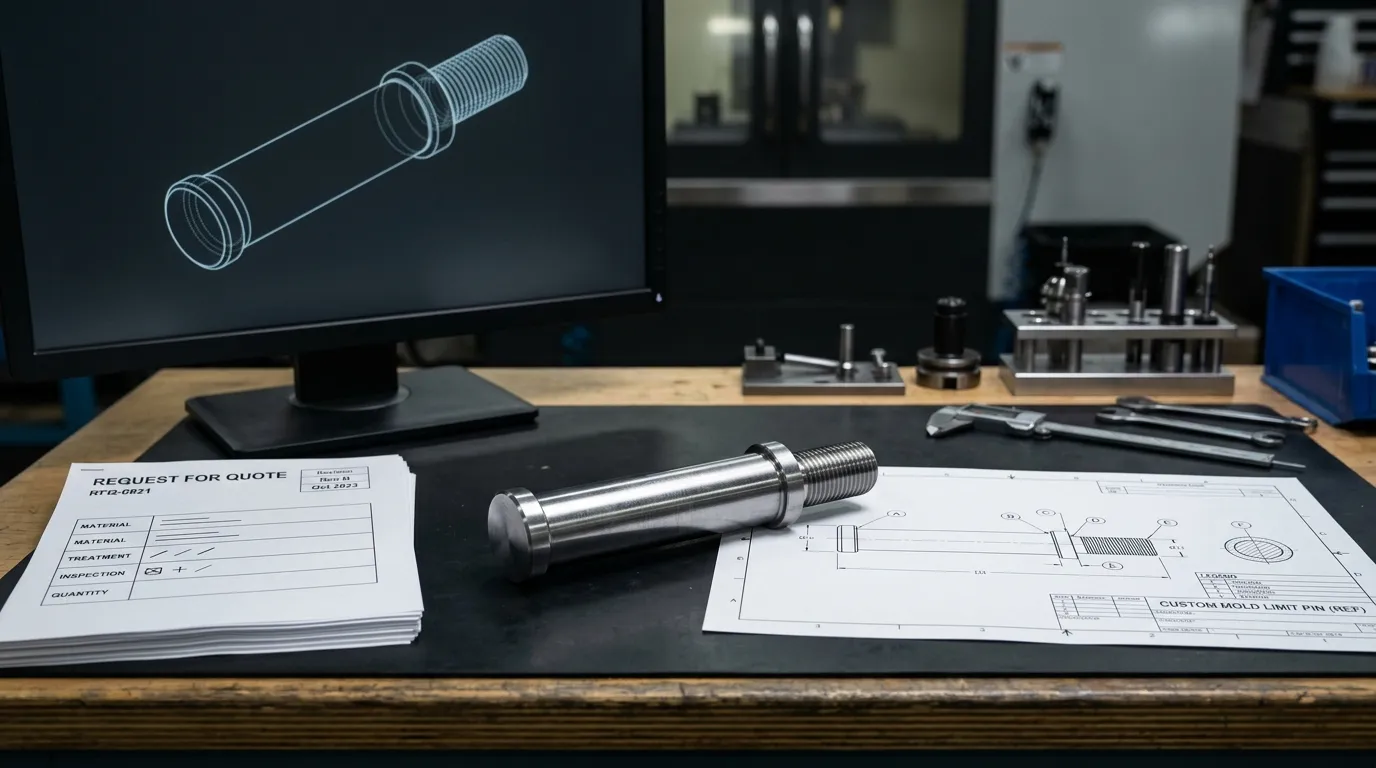
What a Quote-Ready Limit Pin Package Must Contain
A complete custom mold limit pin RFQ normally includes the following information:
| Category | Required information | Why the supplier needs it |
|---|---|---|
| Document control | Part number, drawing revision, units and applicable drawing standard | Establishes which design controls the quotation |
| Pin function | Installation position, movement, stop condition and contact direction | Explains which features are functionally critical |
| Geometry | Overall length, functional length, diameters, shoulders, threads and secondary features | Defines the manufactured component |
| Interfaces | Mating bore, plate thickness, seat, retention method and installation access | Clarifies fit, seating and assembly |
| Material and processing | Material grade, heat treatment, hardness, grinding and surface treatment | Defines the required finished condition |
| Tolerances | Individual tolerances, general tolerance, fit and critical-to-quality features | Determines process and inspection requirements |
| Quality documents | Inspection reports, certificates or first-article requirements | Ensures required documentation is included in the price |
| Commercial data | Quantities, price breaks, destination, delivery date and packaging | Allows the supplier to prepare a complete commercial offer |
| Quote controls | Required assumptions, alternatives, exclusions and deviations | Makes quotations easier to compare |
The technical drawing and commercial RFQ should remain separate documents, but they must use the same part number and revision.
Define the Pin’s Function and Mold Interfaces First
A supplier should not have to determine the component’s purpose from its name alone. Terms such as limit pin, stop pin, return pin, guide pin and core pin may be used differently across companies.
State what the component controls. For example:
- It limits the opening distance between two mold plates.
- It establishes a repeatable stopping position.
- It contacts a defined plate or stop surface.
- It remains fixed while another component moves.
- It slides within a bore during mold operation.
- It is removable for maintenance or replacement.
The drawing package should identify the mating bore, plate, seat or contact component. Include the plate thickness, seating depth or relevant reference geometry when those details affect fit or functional length.
Also define how the pin is installed and retained. A press-fitted pin, threaded pin and sliding pin require different information. Installation access and removal requirements may also affect the need for a head, thread, flat, groove or internal tool feature.
Broader guidance on guided interfaces, alignment and mating fits belongs with mold pins and bushings. In this RFQ, include only the interface information needed to manufacture and inspect the limit pin correctly.
Use an Assembly View When the Part Drawing Cannot Show the Function
A simple part drawing may not show where the pin seats, which face makes contact or how much of the pin remains engaged in the mold plate.
Add a simplified assembly view or interface sketch when it helps communicate:
- Direction of motion or loading
- Mating bore and plate location
- Seating or shoulder position
- Contact or stop surface
- Retention method
- Installation and removal access
- Functional engagement distance
Reference dimensions in the assembly view should be clearly identified as reference information rather than acceptance dimensions for the pin itself.
Dimension the Limit Pin’s Functional Geometry
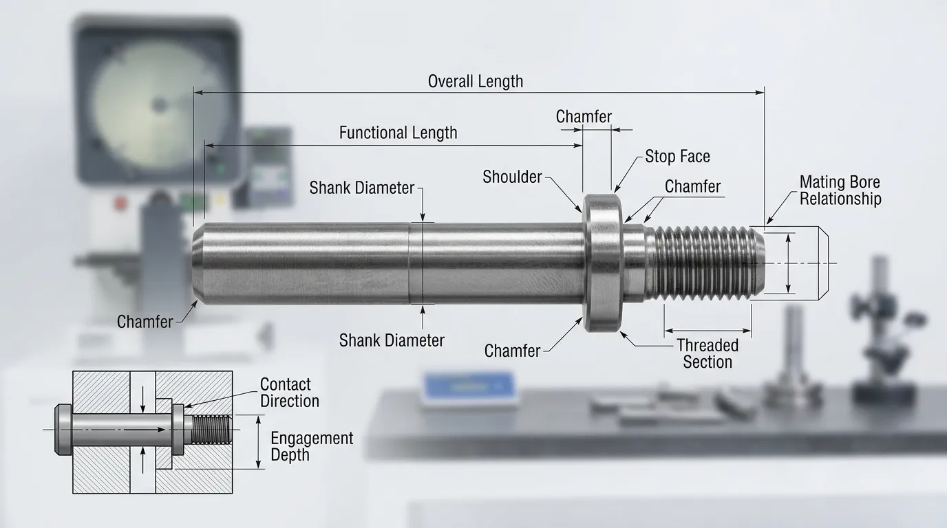
The drawing should define every feature that affects manufacturing, assembly or operation. Avoid relying on a supplier to scale a drawing or infer an unspecified feature from a model.
Typical limit pin drawing items include:
| Feature | What to define | When applicable |
| Overall length | Total manufactured end-to-end length | Always |
| Functional length | Distance controlling contact, engagement or stopping position | When different from overall length |
| Body or shank diameter | Nominal diameter and tolerance | Always |
| Shoulder or flange | Diameter, thickness, location and seating face | For shouldered designs |
| Stop face | Position, orientation and required surface condition | Where the pin establishes a stopping position |
| Thread | System, size, pitch, class, depth and usable engagement | For threaded retention or removal |
| Chamfer or lead-in | Size and angle | For assembly or bore entry |
| Radius or relief | Size and location | Where needed for seating or grinding clearance |
| Groove, flat or hole | Complete size, position and orientation | For retention, removal or orientation |
| Edge condition | Deburring or edge-break requirement | Normally required |
Do not create duplicate dimension chains that control the same feature in different ways. Conflicting dimensions can leave the supplier uncertain about which value takes priority.
Distinguish Overall Length from Functional Length
Overall length describes the complete physical length of the pin. Functional length describes the distance that controls the mold’s movement, stopping position or engagement.
These values may differ when the pin includes:
- A shoulder or flange
- A threaded extension
- A recessed seat
- A head
- An installation projection
- A non-contact end feature
Identify the exact surfaces from which functional length is measured. A dimension from the wrong reference face may produce a pin that matches the overall drawing size but does not stop the mold at the intended position.
Specify Threads and Secondary Features Completely
“Threaded end” or “standard thread” is not a complete requirement. Where a thread is present, define the relevant:
- Metric or imperial thread system
- Nominal size
- Pitch or threads per inch
- Internal or external thread
- Thread class or tolerance
- Right-hand or left-hand direction
- Thread depth
- Usable engagement length
- Thread relief or runout, if functionally important
Grooves, flats, cross-holes and tool-access features also need complete size and location information. If orientation matters relative to another feature, define that relationship rather than leaving it to visual interpretation.
Specify Fit, Tolerances, Datums and Critical Features
A pin diameter cannot be evaluated independently from the bore or plate that receives it. State whether the intended condition is a clearance, transition or interference fit, and define the mating feature that controls that relationship.
Do not assume the supplier will know the intended fit from the component name.
The drawing should include:
- Individual tolerances for functional dimensions
- A general tolerance for unspecified dimensions
- Fit requirements for mating diameters
- Datums where orientation or geometric relationships matter
- Critical-to-quality dimensions that require focused control
- Geometric tolerances only where function justifies them
- An inspection method suitable for the requested tolerance
The drawing should identify the standard governing its dimensional and geometric-tolerance language. ASME Y14.5 and ISO 1101 provide different but established frameworks for geometric tolerancing. Do not mix conventions without defining how the drawing should be interpreted.
Possible geometric controls may include straightness, runout, cylindricity, perpendicularity or position. They should be used only when the controlled relationship affects fit, movement, contact or inspection.
Mark Critical-to-Quality Dimensions Instead of Tightening Everything
Not every dimension requires the same level of control. Identify the features that directly influence:
- Fit with the mating bore
- Seating against a plate
- Stopping position
- Alignment
- Thread engagement
- Replacement interchangeability
These are the critical-to-quality, or CTQ, features. They may require tighter control or recorded inspection results.
Non-critical features can often remain under a suitable general tolerance. Applying unnecessarily tight tolerances to every dimension can increase production and inspection effort without improving the pin’s function.
Define Material, Heat Treatment, Hardness and Surface Condition
Avoid material notes such as “tool steel,” “hardened steel” or “equivalent material.” A quote-ready drawing should state the exact material grade and the governing material specification.
Also define whether alternative grades are:
- Prohibited
- Allowed without further approval
- Allowed only as separately quoted alternatives
- Subject to written buyer approval
Where heat treatment is required, specify the measurable final condition rather than using a broad instruction such as “heat treat.”
A complete hardness requirement may need:
- Hardness scale
- Acceptable range
- Required condition after processing
- Test location
- Case depth, where applicable
- Documentation requirement
For Rockwell hardness, ASTM E18 provides standardized testing requirements. The drawing or RFQ should still identify the required scale, range and reporting scope.
Surface requirements should be assigned to specific features. Replace “smooth finish” with a measurable roughness requirement on the actual sliding, seating or contact surface.
Where coating or another surface treatment is required, define:
- Treatment type
- Surfaces to be treated
- Masked or untreated areas
- Dimensional allowances
- Whether inspection applies before or after treatment
SunshinePro’s published Mold Limit Pin page describes one listed configuration using S45C/45# steel, precision-ground outside diameters, threaded features, vacuum heat treatment and 15–17 HRC. These are specifications for that published configuration, not default requirements for every custom limit pin.
State the Final Inspection Condition
The drawing should make clear whether dimensions and tolerances apply after all required processing.
This matters when heat treatment, coating or grinding can change the part’s size or surface condition. A useful final-condition note should clarify:
- Which dimensions apply after heat treatment
- Which surfaces are finish-ground
- Whether coating thickness is included in the final dimension
- Which areas require masking
- Whether an intermediate machining allowance is needed
Without this clarification, the buyer and supplier may inspect the same feature at different production stages.
Control the Drawing, Model and Supporting Files
The 2D drawing should normally control tolerances, material, treatment, finish, inspection notes and revision status. A 3D model can support nominal geometry, but it should not be the only source of acceptance requirements unless a model-based definition system has been formally established.
Use each file for a defined purpose:
| File | Main purpose | Use when |
| Controlled PDF drawing | Dimensions, tolerances, notes, material, treatment and inspection | Normally required |
| STEP model | Nominal geometry and feature interpretation | Geometry is difficult to communicate in 2D |
| Assembly view | Mating interfaces, motion, seating and contact | Functional relationships are unclear |
| Photograph | Visual reference or identification | Supporting an existing-part replacement |
| Physical sample | Reference for form or existing condition | Supplementing, not replacing, controlled requirements |
All files should show the same part number and revision. Remove obsolete drawings and models before sending the RFQ.
The package should also state which file controls if a model and drawing conflict. ASME Y14.100 provides established practices for engineering drawings and revisions, while ISO 7200 covers document-header and title-block data.
When a 2D Drawing Is Enough
A complete 2D drawing may be sufficient for a simple axisymmetric pin produced through turning and grinding.
It must still define:
- All diameters and lengths
- Shoulders and seating features
- Threads and secondary features
- Tolerances and fits
- Material and processing
- Surface requirements
- Revision and inspection notes
Add a STEP model when the pin includes non-axisymmetric features, complex geometry or relationships that are difficult to interpret through standard views.
Add Inspection and Documentation Requirements to the RFQ
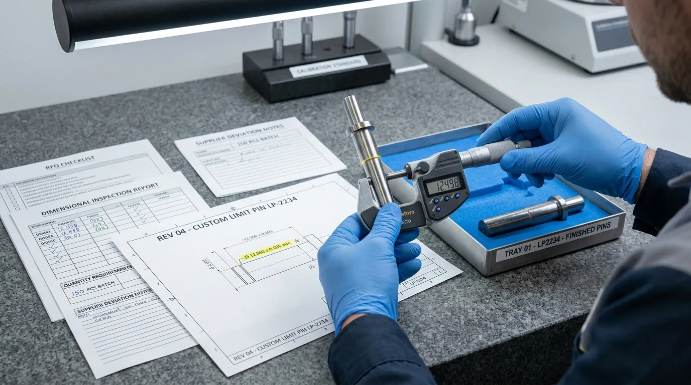
Do not assume that every supplier includes the same inspection records in its base price.
Identify which CTQ dimensions require recorded results and whether you need:
- A dimensional inspection report
- A ballooned drawing
- First-article inspection
- Material certification
- Hardness test results
- Certificate of conformity
- Lot or heat traceability
- A buyer-supplied reporting format
Define the sample size or inspection frequency when necessary. For example, a first article, selected sample or complete batch inspection creates a different scope.
The measurement method should also be suitable for the tolerance and feature. A drawing should not demand a tolerance without considering how that feature can be inspected reliably.
Broader guidance on tolerance, steel, finish and supplier quality control is covered under precision mold parts. Keep this RFQ focused on the documents and measurements required for the specific limit pin.
Include the Commercial Information Needed for Comparable Quotes
A technically complete drawing is not a complete RFQ. Suppliers also need enough commercial information to calculate setup, production, inspection, packaging and delivery costs.
Include:
- Prototype or sample quantity
- Initial production quantity
- Forecast or annual volume, where relevant
- Required quantity breaks
- Requested sample delivery date
- Requested production delivery date
- Delivery destination
- Currency
- Applicable delivery terms
- Packaging and labeling requirements
- Rust-prevention requirements
- Traceability requirements
- Required quotation-validity period
- Whether setup, inspection, freight or samples should be priced separately
Ask suppliers to separate standard production pricing from optional services or expedited delivery. This makes the quotation easier to evaluate and prevents optional documentation from being hidden inside the unit price.
Require Suppliers to State Assumptions, Alternatives and Deviations
Two quotations are not directly comparable if the suppliers have priced different technical scopes.
Require each supplier to list:
- Material substitutions
- Tolerance deviations
- Alternative heat treatments or finishes
- Excluded inspection reports
- Different packaging assumptions
- Tooling or setup charges
- Buyer-supplied responsibilities
- Delivery assumptions
- Features that require clarification
Alternative materials or processes should be quoted separately from the specified requirement.
Also distinguish between a budgetary quotation and a production quotation. A budgetary price may rely on incomplete information and supplier assumptions. A production quotation should refer to a controlled drawing revision and state all deviations clearly.
No supplier change should become part of the order without written buyer approval.
Final Pre-RFQ Drawing Checklist
Before sending the package, confirm the following:
- The part name, part number and drawing revision are correct.
- Units and the applicable drawing standard are identified.
- The pin’s function and installation location are clear.
- The mating bore, plate, seat or contact surface is shown or described.
- Overall length and functional length are distinguished.
- Body diameter and mating fit are defined.
- Shoulders, heads, flanges or seating features are fully dimensioned.
- Threads include size, pitch, class, depth and engagement information.
- Grooves, flats, holes, chamfers and radii are complete.
- Functional dimensions have appropriate tolerances.
- A general tolerance covers unspecified dimensions.
- CTQ features are identified.
- GD&T is used only where function requires it.
- The exact material grade and standard are stated.
- Material substitution rules are clear.
- Heat treatment and hardness requirements are measurable.
- Surface roughness is assigned to defined surfaces.
- Coating, masking and dimensional allowances are clear.
- The final inspection condition is stated.
- The PDF drawing, model and RFQ use the same revision.
- The controlling document is identified.
- Inspection reports and certificates are specified.
- Quantities and price-break requirements are included.
- Delivery, destination and packaging requirements are included.
- Suppliers are asked to list assumptions and deviations.
- Obsolete files have been removed from the RFQ package.
Submitting a Custom Limit Pin Drawing for Supplier Review
SunshinePro states that it supports customized mold components based on customer drawings. Its Mold Limit Pin product page also states that non-standard sizes can be customized and describes a workflow covering drawing submission, design review, quotation, processing, inspection and delivery.
A supplier review may identify missing dimensions, difficult inspection requirements or manufacturing alternatives. Any proposed change should remain clearly documented and subject to buyer approval.
Once the latest drawing revision, quantity requirements, material and processing specifications, inspection scope and delivery details are ready, you can send the package for review and request a quotation.
Share:


Written By Tonmoy
NEWS
GET SERVICE
With quality parts to meet every budget and friendly staff trained to make your visit informative and hassle free.
