



Mold Limit Pin Design Guide: Function, Geometry, and Loading
A mold limit pin is a positive mechanical stop that restricts the travel of an ejector plate, slider, stripper plate, or another moving mold member. Its purpose is to establish a repeatable stopping position and transfer the resulting load into a supporting plate or stop surface.
That sounds simple, but selecting a pin by diameter and length alone is risky. The designer must consider where the force comes from, how quickly the moving assembly reaches the stop, which surface receives the load, and whether several pins will contact at the same time. Compression may not be the controlling failure mode. Contact indentation, bending, buckling, thread damage, impact, or unequal load sharing may govern instead.
Limit pins are one specialized category within the broader system of mold standard parts (inferred). This guide focuses only on their function, geometry, loading, tolerances, and specification.
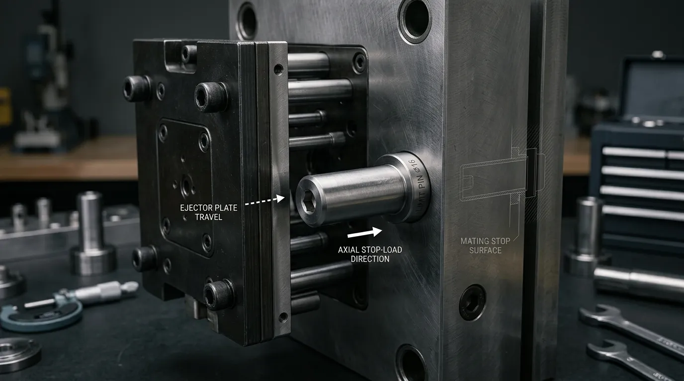
What a Mold Limit Pin Does—and What It Does Not Do
A mold limit pin restricts mechanical travel. In a typical ejector assembly, the pin establishes the point at which the ejector plate or ejector retainer plate must stop moving. Similar stop features may be used for sliders, stripper plates, or other moving components.
The terminology is not fully standardized across suppliers. Depending on the catalog or mold-building convention, related parts may be called:
- mold limit pins;
- mould stop pins;
- stop pins;
- stop buttons;
- limit blocks;
- garbage pins or trash pins.
These terms can describe different geometries or functions. The assembly drawing should therefore define what the component contacts, which movement it limits, and how it is retained. A supplier name alone is not enough to establish the design function.
A mold limit pin should not normally be treated as the primary component that aligns the two mold halves. That function belongs to the guide system. SunshinePro’s guide on mold pins and bushings explains how guide posts and bushings control mold alignment and movement between the mold halves.
Common Applications of a Positive Travel Stop
The ejector system is the most common context for a mold limit pin. The pin can establish the final ejector stroke, prevent excess plate movement, or provide a defined contact point before another component is overloaded.
Other applications may include:
- limiting slider or side-action travel;
- stopping a stripper plate at a controlled position;
- restricting movement within a secondary plate assembly;
- providing a replaceable contact point in a repeated stop condition.
The first design question is not “What diameter should the pin be?” It is “Which component is moving, and where does its load go after contact?”
The complete load path may include the actuator, moving plate, limit pin, mounting feature, mating stop surface, backing plate, and nearby support pillars. Weakness in any part of that path can cause failure even when the pin body appears large enough.
Limit Pin Versus Other Mold Components
| Component | Primary function | Normally carries the final stop load? |
|---|---|---|
| Limit pin or stop pin | Restricts mechanical travel | Yes |
| Stop button | Provides a compact stop surface, commonly in an ejector assembly | Yes |
| Limit block | Restricts travel through a larger block-shaped contact area | Yes |
| Guide pin and bushing | Guides and aligns mold movement | No, not as the intended final travel stop |
| Return pin | Assists ejector-system return and guidance | Not normally |
| Ejector pin | Transfers ejection force to the molded part | No |
| Support pillar | Supports plates against structural deflection | Not as a travel stop |
| Trash or garbage pin | Supports or spaces parts of the ejector assembly and helps reduce debris-related interference | Depends on the specific design and terminology |
| Limit switch | Detects position electrically | No, unless combined with a separate mechanical stop |
A limit block may be more suitable than a cylindrical pin when the design needs a larger contact area, lower local pressure, or greater resistance to plate tilt. A limit switch can confirm that a position has been reached, but it does not automatically provide a load-bearing mechanical stop.
Define the Load Case Before Selecting the Pin
A mold limit pin cannot be designed reliably without a defined operating condition. The required diameter, contact area, effective length, material, and mounting method all depend on the load case.
Collect the following information before selecting the component:
- Controlled movement: Identify the ejector plate, slider, stripper plate, or other member being stopped.
- Required travel: Define the final stop position from functional reference surfaces.
- Maximum actuator force: Determine the hydraulic, pneumatic, spring, or mechanical force that may remain after contact.
- Moving mass: Include the relevant plate assembly and attached components.
- Approach velocity: Establish how quickly the assembly reaches the stop.
- Deceleration method: Confirm whether the system slows before contact or relies on the pin to stop the moving mass.
- Pin quantity and layout: Record how many stops are intended and where they are positioned.
- Plate stiffness: Consider plate thickness, support spacing, load position, and expected deflection.
- Available envelope: Check the maximum diameter, length, head size, and service access.
- Operating environment: Consider temperature changes, lubrication, contamination, and corrosion exposure where relevant.
- Maintenance requirements: Define whether the pin or mating insert must be replaceable.
- Failure consequence: Determine what could be damaged if the stop fails or moves beyond its intended position.
These inputs should come from the actual assembly and operating sequence. A standard catalog size should not be accepted simply because it fits the available hole.
Static Stop, Repeated Contact, or Dynamic Impact?
Not every limit pin sees the same type of loading.
| Load condition | What happens | Main design concerns |
| Static holding load | The plate is already stopped and continues pressing against the pin | Compression, contact pressure, thread or shoulder load |
| Repeated low-speed contact | The plate contacts the stop during each cycle at controlled speed | Contact wear, indentation, fatigue, height consistency |
| Dynamic impact | The pin rapidly decelerates a moving assembly | Impact energy, peak force, bending, surface damage, cracking |
| Combined load | The assembly impacts the stop and the actuator continues applying force | Impact followed by sustained compression |
Static actuator force does not describe the full load when a moving assembly strikes the stop. The energy involved depends on moving mass and velocity, while peak force also depends on stopping distance, stiffness, and damping.
A small, rigid pin should not be expected to absorb unrestricted kinetic energy repeatedly. Where impact is significant, the mold or machine should use controlled deceleration, cushioning, or another suitable motion-control method. There is no reliable universal impact multiplier that applies to every mold.
Mold Limit Pin Geometry and Placement
The pin’s overall length is only one part of its geometry. The designer must identify the dimensions that control stopping position, load capacity, contact pressure, mounting, and replacement.
Important features include:
- installed stop height;
- body diameter;
- smallest reduced diameter;
- exposed or unsupported length;
- end-contact diameter;
- contact-face flatness;
- head, shoulder, or flange;
- threaded section;
- thread engagement;
- counterbore or seating geometry;
- transition radii;
- chamfers and edge breaks;
- retaining method;
- access for removal.
The installed stop height is the functional dimension. It is measured through the complete assembly from the pin’s seating reference to the surface that makes contact. It may differ from the component’s overall manufactured length.
A pin can be dimensionally correct as an individual part but still produce the wrong stop position because of seat depth, plate thickness, counterbore depth, debris, burrs, or variation in the mating surface.
Diameter, Contact Face, and Effective Length
Three dimensions deserve separate attention.
Body diameter affects the cross-sectional area available to carry compression. It also has a strong effect on bending stiffness and buckling resistance. The nominal body diameter may not be the governing section if the pin contains a thread root, relief, groove, or reduced shank.
End-contact diameter controls how the load enters the mating plate. A small contact face can create high local pressure even when the pin’s average compressive stress is low. Partial contact caused by angular error makes the pressure more concentrated.
Effective unsupported length affects the pin’s tendency to bend or buckle. It is not automatically equal to the overall length. The designer must consider how the pin is supported, where it leaves the mounting plate, and where the load is applied.
A short, well-supported pin may be governed by contact pressure. A long, slender, exposed section may require a column-stability check even when its compressive stress appears acceptable.
Head, Shoulder, Thread, and Retention Features
The pin body is not the only part that transfers load. A shouldered pin may load the seating face beneath the shoulder. A threaded pin may place the thread, thread runout, or first engaged thread under significant stress.
Check the following:
- whether the shoulder seats fully on a flat surface;
- whether the counterbore supports the head without edge contact;
- whether the thread engagement is sufficient for the applied load;
- whether the smallest thread-root area governs the section;
- whether a sharp diameter transition creates a stress concentration;
- whether installation torque can damage the thread or distort the seat;
- whether the pin can be removed without dismantling unrelated parts.
Threads should retain the component rather than compensate for poor seating. If the stop load should pass through a shoulder, confirm that the shoulder contacts before the thread becomes the primary load-bearing feature.
Number and Placement of Limit Pins
Multiple pins can stabilize a plate and distribute load, but only when their positions and installed heights are controlled.
Place pins with reference to:
- the center of the applied load;
- actuator locations;
- the plate’s structural supports;
- areas of expected plate bending;
- mold cavities and ejector-force distribution;
- available edge distance;
- access for inspection and replacement.
A symmetrical layout can reduce plate rotation, but symmetry alone does not ensure equal loading. If the plate bends or one pin is slightly taller, the first pin to contact may initially carry most of the force.
The designer should not divide the total force equally by the number of pins without checking whether equal contact is realistic. A larger stop button or limit block may be preferable when concentrated pin loading causes unacceptable plate deformation or contact pressure.
How to Check Mold Limit Pin Loading
A practical load review should follow a defined sequence:
- Establish the maximum credible design load.
- Determine how that load is distributed among the pins.
- Identify the smallest load-bearing cross-section.
- Check nominal axial compression.
- Check contact stress at the pin end and mating surface.
- Screen long exposed sections for buckling.
- Check eccentricity and bending.
- Review shoulders, threads, and retaining features.
- Evaluate dynamic impact separately from static force.
- Confirm that tolerances and plate deflection do not invalidate the load-sharing assumption.
Final acceptance requires verified material properties, operating data, boundary conditions, and an engineering-approved safety basis. Simplified calculations are useful for identifying likely failure modes, but they do not replace system-level validation.
Axial Compression and the Governing Cross-Section
For a centrally loaded pin, nominal compressive stress can be expressed as:
[
\sigma_c = \frac{F}{A}
]
where:
- (\sigma_c) is nominal compressive stress;
- (F) is the design load assigned to the pin;
- (A) is the effective load-bearing cross-sectional area.
Use the smallest relevant section, not automatically the nominal body area. A threaded root, relief, cross-hole, groove, or reduced shank may control the result.
The assigned load must also be realistic. If four pins are installed but manufacturing variation allows one pin to contact first, using one-quarter of the total force may be unconservative.
The calculated stress should be compared with verified material properties for the specified material and heat-treatment condition. Do not use a generic steel value or a catalog hardness number as a substitute for the required strength data.
Contact Stress at the Pin End and Stop Surface
Contact stress is localized where two bodies press against each other. Small or imperfect contact areas can produce stresses much higher than the average compression in the pin body.
The Air Force Stress Analysis Manual material on bearing and contact stress explains that concentrated contact can create high local stress, particularly when the initial contact area is small. Its simplified contact treatment applies mainly to static or low-velocity conditions, so a separate impact review is needed for rapid contact.
Check both sides of the interface:
- the pin end;
- the mating plate or insert;
- any coating or hardened layer;
- the supporting material beneath the contact surface.
A hard pin contacting a much softer plate may leave the pin intact while permanently indenting the plate. Increasing pin hardness alone does not solve that problem. The design may need a larger contact face, a harder replaceable insert, a limit block, or a different stopping arrangement.
Flatness and alignment matter as well. If only one edge of the pin face contacts, the actual bearing area becomes much smaller than the nominal circular area.
Buckling and Misalignment-Induced Bending
A pin under axial compression can become unstable if its exposed section is sufficiently slender. The classic Euler approach relates column stability to elastic modulus, effective length, cross-sectional stiffness, and end restraint.
The Air Force Stress Analysis Manual section on simple columns provides the underlying relationships used for long, concentrically loaded columns. Those assumptions must be checked before applying the formula to a mold component.
Buckling becomes more important when:
- the exposed length is large relative to diameter;
- the pin has a reduced section;
- lateral support is limited;
- the end-restraint condition is uncertain;
- the load is nearly axial but not perfectly centered.
Real mold assemblies may introduce eccentric loading through plate tilt, angular error, seat variation, or partial-face contact. An eccentric force creates a bending moment in addition to compression.
This explains why a pin may bend even though a basic axial stress calculation shows a large margin. Perpendicular seating, controlled clearances, plate stiffness, and simultaneous contact all help keep the load close to the pin axis.
Dynamic Impact and Unequal Load Sharing
Impact should be treated as an energy and deceleration problem.
The moving assembly has kinetic energy before contact:
[
E_k = \frac{1}{2}mv^2
]
where:
- (m) is the effective moving mass;
- (v) is the velocity immediately before contact.
That energy must be absorbed through elastic deformation, damping, cushioning, controlled deceleration, or local deformation at the stop. A very short stopping distance can create a high peak force even when the moving mass appears modest.
The designer therefore needs more than the actuator’s rated force. Required inputs include approach velocity, moving mass, machine sequence, cushioning, structural stiffness, and the actual stopping distance.
Load sharing creates another uncertainty. Multiple limit pins may not contact simultaneously because of:
- length variation;
- seat-depth variation;
- burrs or contamination;
- plate flatness error;
- plate deflection;
- thermal expansion;
- angular misalignment.
A conservative design may need to assume that fewer pins carry the initial load. For significant impact or flexible plates, system-level structural or dynamic analysis may be more appropriate than an equal-load assumption.
Tolerances That Control Stop Height and Load Sharing
The final ejector or slider position depends on an assembly-level tolerance stack, not one isolated pin dimension.
The stack may include:
- pin overall length;
- shoulder or head thickness;
- seat depth;
- counterbore depth;
- mounting-plate thickness;
- spacer dimensions;
- mating-plate position;
- contact-face flatness;
- assembly clearance;
- plate deflection.
The purpose of the tolerance analysis is to determine the possible minimum and maximum installed stop height. It should also establish how much mismatch can occur among several pins.
ISO 286-1 provides standardized terminology and a code system for linear-size tolerances and fits. It can support fit and tolerance communication, but the designer must still assign functional limits based on the mold assembly.
Important geometric controls may include:
- flatness of the pin seat;
- flatness of the mating stop surface;
- parallelism between opposing stopping surfaces;
- perpendicularity of the pin axis;
- concentricity or runout where rotating machining operations affect the functional geometry;
- matched installed height for a set of pins.
SunshinePro’s current mold limit-pin product page publishes specific diameter, length, material, and hardness information for its displayed component. Those figures should be treated as product-specific data rather than universal design tolerances.
For broader supplier and inspection considerations, see the guide to precision mold parts.
Why Equal Pin Length Does Not Guarantee Equal Load
Two pins can have the same measured overall length and still contact at different times.
Possible causes include:
- different seat depths;
- burrs below one shoulder;
- debris on one contact face;
- plate warpage;
- counterbore variation;
- local plate deflection;
- thermal growth;
- uneven support beneath the plate.
The installed assembly should therefore be checked for actual contact, not only individual pin length. Contact marking, installed-height measurement, controlled assembly references, and plate-flatness inspection can reveal early-contact conditions.
If one pin contacts first, it may carry a large share of the initial load until the plate deflects enough for the other stops to engage.
Common Failure Modes and What They Indicate
Visible damage often identifies which part of the design needs to be reviewed.
| Symptom | Possible causes | Required checks |
| Mushroomed or flattened pin end | Excessive contact stress, repeated impact, insufficient contact area | Contact load, face area, approach velocity, material condition |
| Indented mating plate | Plate too soft, contact area too small, concentrated or edge loading | Plate material, hardness, flatness, insert design |
| Bent pin | Eccentric loading, plate tilt, excessive clearance, side contact | Perpendicularity, support, alignment, plate stiffness |
| Buckled pin | Excessive unsupported length or insufficient diameter | Effective length, end restraint, slenderness |
| Chipped or cracked end | Impact, brittle condition, sharp edge, poor heat-treatment balance | Toughness, edge geometry, dynamic load, material records |
| Damaged thread | Load passing through thread, insufficient engagement, poor seating | Thread-root area, engagement, shoulder contact |
| Fretting or uneven face wear | Repeated small movement, partial contact, vibration | Contact pattern, preload, flatness, surface condition |
| One pin wears faster than the others | Height mismatch or unequal plate deflection | Installed heights, plate support, load distribution |
| Final stroke changes over time | Indentation, loosening, wear, debris, seat damage | Stop height, seating surfaces, retention, contact face |
A damaged limit pin should not automatically be replaced with a harder version. The failure may originate in the stop surface, plate stiffness, approach speed, mounting method, or tolerance stack.
Replacement intervals should be based on inspection and operating history. A fixed number of molding cycles cannot be applied reliably across different molds, loads, speeds, materials, and maintenance conditions.
Standard or Custom Mold Limit Pin?
A standard component is appropriate only when its geometry and verified specifications satisfy the actual design case.
| Standard component may be suitable when | A custom drawing may be justified when |
| Catalog diameter and length fit the assembly | Stop height or envelope is non-standard |
| Load and contact checks are acceptable | A special head, shoulder, thread, or contact face is required |
| Installed-height tolerance can be achieved | Several pins require tightly matched installed heights |
| The mating surface is compatible | Contact pressure requires a larger or modified face |
| Replacement interchangeability is controlled | The load includes significant impact or eccentricity |
| Material and hardness meet the requirement | A documented material or heat-treatment condition is required |
| Mounting and service access are acceptable | A replaceable insert or unusual retention method is needed |
SunshinePro states that it supplies standard mold components and custom parts based on drawings. Its current mold limit pin product page lists S45C and published dimensional and hardness information for the displayed product. It also states that standard and non-standard sizes are available.
Those product-page values should be checked against the actual mold requirements. S45C, one hardness range, or one tolerance set should not be assumed to suit every stop condition.
When a Standard Component Is Usually Appropriate
A standard pin is a practical choice when:
- its installed height matches the required stroke;
- its weakest section passes the required load checks;
- its contact face is suitable for the mating plate;
- its mounting feature transfers load correctly;
- its tolerance supports simultaneous contact;
- replacement parts remain dimensionally interchangeable.
Standardization can simplify maintenance, but only when the functional dimensions are controlled. A nominally similar part is not necessarily interchangeable if the shoulder, seat, contact face, or installed height differs.
When a Custom Drawing Is Justified
Custom geometry becomes more reasonable when the assembly requires:
- an unusual stop height;
- a restricted installation envelope;
- a special shoulder or flange;
- non-standard threading;
- a larger contact face;
- a matched set of pins;
- a replaceable stop interface;
- controlled material or heat treatment;
- tighter functional tolerances;
- special inspection documentation.
The custom drawing should describe the pin’s function, not only its shape. A supplier cannot evaluate the design load from a part drawing that omits the operating force, movement, contact condition, and mating structure.
Mold Limit Pin Drawing and Inspection Checklist
A production drawing should communicate the dimensions and requirements that affect function.
Include the following where applicable:
Functional and Assembly Information
- component being stopped;
- direction of movement;
- required travel;
- installed stop height;
- reference surfaces;
- number and location of pins;
- mating stop surface;
- available installation space;
- removal and replacement method.
Geometry
- overall length;
- functional installed length;
- body diameter;
- smallest reduced diameter;
- end-contact diameter;
- head, flange, or shoulder dimensions;
- thread size, class, length, and runout;
- counterbore or seat dimensions;
- transition radii;
- chamfers and edge breaks.
Tolerances and Surface Requirements
- length tolerance;
- matched-height requirement;
- diameter tolerance and fit;
- contact-face flatness;
- perpendicularity of the pin axis;
- parallelism between functional faces;
- surface finish where it affects fit, wear, or contact;
- assembly-level stop-position tolerance.
Material and Verification
- material specification;
- heat-treatment condition;
- required hardness and test location;
- material certificate requirement, if needed;
- heat-treatment record, if needed;
- dimensional inspection report, if needed;
- traceability or revision requirements.
Operating Data
- maximum static force;
- moving mass;
- approach velocity;
- stopping or cushioning method;
- expected contact frequency;
- operating temperature range where relevant;
- contamination or corrosion exposure;
- consequence of stop failure.
Inspection should cover more than the loose component. The assembled system may also need checks for:
- installed stop height;
- simultaneous contact;
- seating cleanliness;
- contact pattern;
- plate flatness;
- thread condition;
- pin loosening;
- face indentation;
- bending or cracking;
- uneven wear among pins.
Information to Send for a Design or Quotation Review
A useful supplier-review package should include:
- the limit-pin drawing;
- an assembly section showing the moving and stationary members;
- the required stop position;
- pin quantity and layout;
- static actuator force;
- moving mass and approach velocity;
- deceleration or cushioning details;
- mating-surface material;
- material and hardness requirements, if established;
- tolerance and inspection requirements;
- expected replacement or interchangeability needs.
SunshinePro states that it produces customized mold components from drawings. For a standard or custom limit-pin inquiry, submit the drawing and operating requirements through the SunshinePro contact page. A complete load case and assembly view will support a more useful manufacturing review than isolated diameter and length values.
Share:


Written By Tonmoy
NEWS
GET SERVICE
With quality parts to meet every budget and friendly staff trained to make your visit informative and hassle free.
