



Mold Limit Pins for Automotive Molds: Load, Wear, and Precision
Mold limit pins for automotive molds act as mechanical stops. They establish or restrict the travel of an ejector plate, slider, side action, or another moving mold component. Their performance depends on more than pin diameter or material. The stopped mechanism, contact speed, pin support, mating surface, load distribution, and required endpoint all affect the result.
Limit pins belong to a wider system of mold standard parts (inferred), but they should not be selected using broad catalog criteria alone. A suitable stop must carry the intended reaction without bending, loosening, damaging the mating plate, or gradually changing the mechanism’s final position.
There is no universal pin diameter, hardness, fit, or replacement interval for every automotive mold. Selection starts by defining the movement being controlled.
What a Mold Limit Pin Controls—and What It Does Not
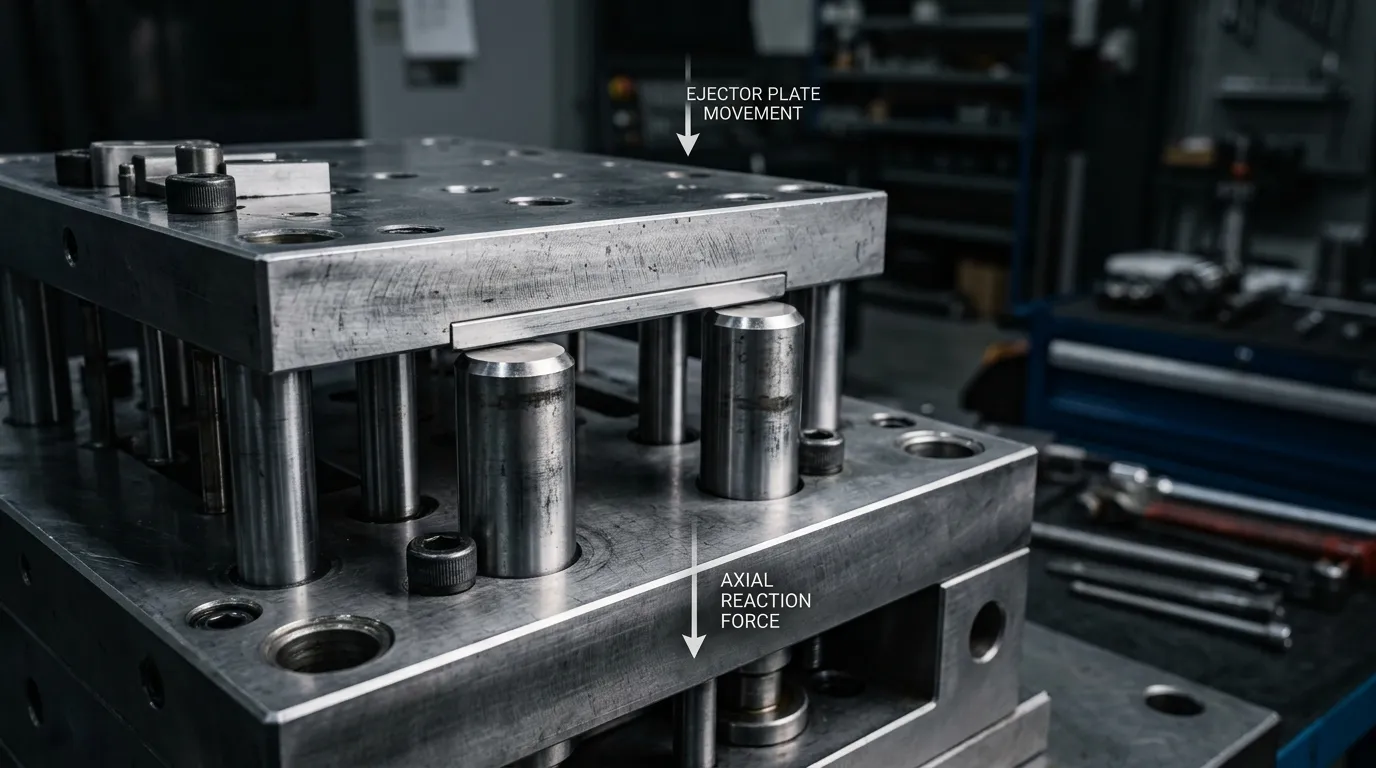
A mold limit pin is a fixed mechanical stop. When the moving mold component reaches the designed endpoint, it contacts the pin or a surface supported by the pin. The stop reaction then passes into the mounting plate and surrounding mold structure.
“Limit pin” and “stop pin” are often used for similar components, but supplier terminology is not always consistent. The drawing should therefore state the actual function:
- which component moves;
- the direction of movement;
- the required endpoint;
- which surfaces make contact;
- whether the stop sees gradual loading or repeated impact.
A limit pin should also be separated from other cylindrical mold components.
| Component | Primary function | Typical interaction | Main selection concern |
|---|---|---|---|
| Limit pin or stop pin | Restricts travel at a defined endpoint | Moving plate or mechanism contacts the stop | Contact load, support, wear, and effective stop length |
| Guide pin and bushing | Guides and aligns mold sections during movement | Guide pin engages its matching bushing | Alignment, engagement, clearance, lubrication, and wear |
| Ejector pin | Pushes the molded component from the cavity or core | Pin face contacts the molded part | Ejection force, placement, surface marks, and retention |
| Return pin | Returns or resets the ejector assembly | Mold closing or a return mechanism moves the ejector system back | Return stroke, interference, and reliable reset |
| Limit block | Provides a broader mechanical stop | Plate or mechanism contacts a larger stop face | Contact area, space, support, and replacement access |
Guide pins and bushings are responsible for guided mold movement and mold-half alignment. Their design belongs to the separate subject of mold pins and bushings. A limit pin may help maintain a repeatable mechanism endpoint, but that does not make it a substitute for a guide system.
Define the Automotive Mold Mechanism Before Selecting the Stop
The first design question is not “Which pin size should be used?” It is “What movement must be stopped?”
An automotive mold may contain several moving systems, each with different loading conditions:
- an ejector plate reaching the end of its stroke;
- a slider reaching its open or closed position;
- a side-action mechanism stopping after core withdrawal;
- a moving support or auxiliary plate reaching a controlled endpoint.
Before selecting a stop, define:
- The moving component and its direction of travel.
- The total stroke and required final position.
- The moving mass.
- The expected velocity when contact occurs.
- Any hydraulic, spring, machine, or mechanical force still acting at the endpoint.
- The number and location of stop points.
- The available plate thickness and pin support depth.
- The mating-surface material and contact geometry.
- Access for installation, inspection, adjustment, and replacement.
- Any OEM, Tier, or customer-specific tooling requirements.
Automotive customer specifications may set their own rules for mechanical stops, wear plates, guide systems, movement controls, materials, or documentation. Those requirements should be checked before generic design guidance is applied.
Ejector-Plate Stops
An ejector plate is usually broad and relatively stiff, but it may still deflect under load. If several limit pins are used, their position and effective height affect how the plate reaches the endpoint.
A practical ejector-plate stop arrangement should consider:
- whether the stops are distributed around the loaded area;
- whether the plate can contact all stops at nearly the same time;
- whether one region of the plate bends before another;
- whether the stop reaction is transferred into adequately supported mold structure;
- whether the pins remain accessible after assembly.
If one pin is slightly taller or better supported than the others, it may contact first and carry a disproportionate part of the reaction.
Slider, Side-Action, and Moving-Plate Stops
Horizontal or angled mechanisms introduce additional concerns. A stop pin may receive side load if the slider is not guided correctly or if the contact faces are not square to the direction of travel.
For these mechanisms, verify:
- whether the stop controls the open or closed position;
- whether the contact is axial or angled;
- whether a wear plate or replaceable insert is needed;
- whether an adjustable endpoint is required;
- whether dirt, lubricant, or molding residue can enter the contact area;
- whether the stop can be inspected without major disassembly.
The guide system should control the path of the slider. The stop should control its endpoint. Combining both functions in one unsupported pin increases the risk of bending and uneven wear.
How Load Travels Through the Limit-Pin System
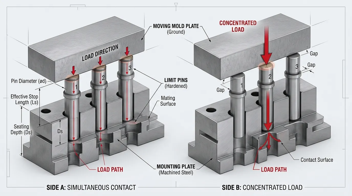
A limit pin does not carry load independently. It is one part of a load path:
moving mechanism → contact face → limit pin or stop → pin seat → mounting plate → mold structure
Every part of that path must support the reaction.
A pin loaded directly along its axis mainly sees compression. A pin contacted off-center or at an angle may also see bending. Bending becomes more significant when the exposed length is large, the mounting support is shallow, or the contact force is not aligned with the pin axis.
The mating surface matters as much as the pin. A small pin end creates a concentrated contact area. Even when the pin itself remains intact, the opposing plate may indent or wear. That indentation changes the effective stopping position.
The surrounding plate must also be stiff enough to support the stop. A strong pin mounted in a thin or flexible plate may still produce inconsistent contact because the plate deflects.
Static Contact Versus End-of-Stroke Impact
A mechanism that settles gradually against a stop creates a different condition from one that strikes the stop at speed.
| Contact condition | Main characteristics | Selection concern |
| Gradual or static contact | Load increases slowly and may remain at the endpoint | Compression, plate support, long-term indentation, and stability |
| Repeated impact contact | Moving mass reaches the stop with measurable velocity | Impact severity, toughness, loosening, deformation, and mating-surface damage |
| Controlled or damped contact | Motion is slowed before reaching the mechanical stop | Residual force, control reliability, and emergency stop capacity |
Moving mass and contact velocity influence the energy reaching the stop. Deceleration distance, damping, machine control, and structural flexibility also affect the contact condition. A final pin design should not be approved from static force alone when repeated impact is possible.
Why Multiple Limit Pins May Not Share Load Equally
Using four stops does not guarantee that each carries one quarter of the load.
Unequal sharing can result from:
- small differences in effective pin height;
- uneven seating;
- plate deflection;
- non-parallel contact surfaces;
- asymmetric stop placement;
- different support stiffness beneath each pin;
- wear or indentation at one contact point.
The tallest or stiffest-supported pin may contact first. It then begins carrying load before the other stops engage. Over time, this can create a repeating pattern: one pin wears or indents faster, the endpoint shifts, and the remaining pins begin contacting under different conditions.
Effective stop height, seating, plate stiffness, and contact pattern should therefore be evaluated together.
Geometry, Material, and Fit Determine Wear and Endpoint Stability
Catalog dimensions describe the part, but they do not fully describe its performance. Diameter, effective length, exposed length, mounting fit, contact geometry, material condition, and the opposing surface all influence the stop.
Diameter, Effective Length, and Unsupported Length
Several dimensions have different functional roles:
| Dimension or feature | Functional effect |
| Pin diameter | Influences stiffness, bearing area in the mounting hole, and resistance to bending |
| Total length | Defines the overall component size but may not equal the functional stop dimension |
| Effective stop length | Controls the final mechanism endpoint |
| Unsupported length | Influences bending sensitivity and rigidity |
| Seating depth | Affects support and positional stability |
| End geometry | Controls contact area and local pressure |
| Shoulder or retention feature | Affects seating, assembly, removal, and repeat positioning |
A long pin with a small exposed diameter is more sensitive to lateral force than a short, well-supported pin of the same material. Increasing hardness alone does not correct an unfavorable load direction or excessive unsupported length.
The mounting-hole fit also needs to match the intended service method. A permanently retained pin, a replaceable maintenance item, and an adjustable stop do not require the same mounting arrangement.
Hardness, Toughness, and the Mating Surface
Hardness can improve resistance to indentation and abrasive wear, but it is not the only material property that matters. Repeated impact also requires adequate toughness. A harder component is not automatically a safer component if it becomes more sensitive to cracking or transfers damage into a softer plate.
The pin and mating surface should be treated as a contact pair. Check:
- pin material and heat-treated condition;
- pin hardness;
- mating-surface material and hardness;
- end-face contact area;
- contact angle;
- expected impact severity;
- whether the mating surface is replaceable.
A hardened wear plate or replaceable insert may be more practical than allowing the stop to contact an expensive mold plate directly. It can localize wear in a serviceable component, provided the insert is adequately supported and secured.
Heat treatment should be defined by the required material condition, not by a generic claim that heat-treated parts are always better. The target hardness, treatment method, distortion control, and verification requirements should be stated where they are functionally important.
Fit, Seating, and Functional Precision
For a limit pin, useful precision means the mechanism reaches a stable, repeatable endpoint. That result depends on more than a tight diameter tolerance.
Important factors include:
- the pin’s effective stop length;
- mounting fit;
- full seating against the reference surface;
- perpendicularity of the pin to the contact direction;
- flatness and condition of the opposing surface;
- height consistency between multiple stops;
- resistance to loosening;
- repeatability after replacement.
The ISO 286 system for tolerances and fits provides standardized terminology for linear-size tolerances and hole-and-shaft relationships. It does not identify one universal fit for every limit pin. The required fit depends on retention, replacement, loading, temperature, plate material, and maintenance needs.
Surface texture should also be specified only where it affects fit, contact, measurement, or wear. Broader information about tolerance, steel, and inspection planning belongs with precision mold parts.
Wear Patterns Show Where the Stop System Is Failing
A worn pin is often a symptom of a wider stop-system problem. Visual damage should be treated as evidence to investigate, not as a complete diagnosis.
| Observation | Possible contributors | Functional risk | What to verify |
| End-face indentation | High local contact pressure, soft material condition, impact, small contact area | Reduced effective stop height | Contact area, hardness, impact condition, mating surface |
| Mushroomed pin end | Plastic deformation from concentrated or repeated loading | Changed endpoint and difficult removal | Material condition, impact severity, end geometry |
| Bent pin | Side load, off-axis contact, excessive unsupported length, poor guidance | Misalignment of contact and unstable endpoint | Load direction, support depth, guide condition |
| One-sided wear | Tilted contact, side loading, plate deflection, poor seating | Uneven load transfer | Contact pattern, perpendicularity, plate stiffness |
| Scoring | Sliding contact, contamination, misalignment, rough mating surface | Accelerated wear and possible seizure | Contact direction, debris, lubrication, surface condition |
| Loose pin | Incorrect fit, repeated impact, damaged mounting hole, poor retention | Endpoint movement and further plate damage | Mounting fit, hole condition, retention method |
| Indented mating plate | Pin harder than the opposing surface, small contact area, insufficient support | Endpoint drift even if the pin appears acceptable | Plate hardness, insert condition, support, contact geometry |
| Uneven wear among several pins | Height mismatch, unequal support, plate deflection | One stop carries load first | Effective heights, seating, spacing, contact sequence |
Wear changes the geometry of the stop system. Material loss from the pin, indentation in the mating surface, or movement inside the mounting hole can all alter the final position without producing a complete fracture.
Replacement should therefore be based on functional condition, dimensional change, contact pattern, and application requirements—not a universal number of molding cycles.
Choose the Right Stop Architecture: Pin, Block, or Adjustable Stop
A cylindrical limit pin is useful when space is limited, the contact direction is controlled, and the required endpoint can be established with a fixed component. It is not automatically the best stop for every mechanism.
| Stop option | Best suited to | Main advantages | Main limitations |
| Fixed limit pin | Compact, defined stop points with controlled axial contact | Simple geometry, replaceable, available in standard or custom forms | Limited contact area; sensitive to side load and support conditions |
| Limit block | Broader contact or higher need for load distribution | Larger contact area, robust support, easier use of replaceable wear faces | Requires more space and accurate mounting surfaces |
| Adjustable stop | Endpoint requiring setup or controlled correction | Allows position adjustment during tool setup or maintenance | Needs secure locking, access, and verification after adjustment |
| Wear insert with stop | Expensive plate requiring a serviceable contact surface | Protects the main plate and simplifies maintenance | Adds components, attachment requirements, and tolerance interfaces |
Sensors or switches may confirm that a mechanism reached a position, but position detection does not automatically replace a correctly designed mechanical stop. The control and mechanical systems should have clearly defined roles.
When a Standard Pin Is Enough—and When Customization Is Justified
A standard pin may be suitable when its geometry, material condition, fit, effective length, contact face, and replacement method match the mold requirement.
Customization may be justified when the application needs:
- a non-standard effective length;
- a special shoulder or mounting feature;
- a larger or shaped contact end;
- a specified material or heat-treated condition;
- tighter control of a functional dimension;
- replacement compatibility with an existing mold;
- customer-specific documentation;
- improved installation or removal access.
Custom does not automatically mean better. It is justified when the standard component cannot satisfy the defined function without compromise.
What to Put on the Drawing or RFQ
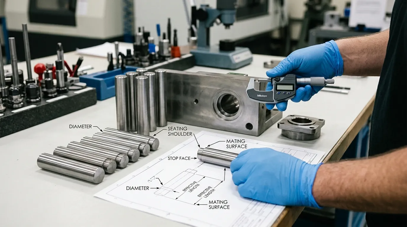
A useful RFQ should describe both the part and the mechanism in which it will operate. Sending only a nominal diameter and length leaves important engineering decisions undefined.
Application information
Include:
- type of moving mechanism;
- stopped component;
- direction of travel;
- total stroke;
- required final position;
- moving mass;
- expected contact velocity or impact condition;
- external hydraulic, spring, machine, or mechanical force;
- number and spacing of stops;
- operating temperature and contamination conditions where relevant;
- applicable automotive customer or tooling specification.
Component definition
Specify:
- pin diameter;
- total length;
- effective stop length;
- unsupported or exposed length;
- end geometry;
- shoulder and seating dimensions;
- mounting-hole relationship;
- fit or retention requirement;
- removal feature if replacement is expected;
- geometric controls needed for seating or contact.
Material and process requirements
State:
- material grade and condition;
- heat-treatment requirement;
- target hardness where justified;
- functional surface requirements;
- mating-surface material and hardness;
- need for a wear plate or replaceable insert.
Inspection and documentation
Depending on the project, request:
- dimensional inspection results;
- hardness verification;
- material documentation;
- drawing revision control;
- part or batch identification;
- first-article or sample approval;
- confirmation of replacement interchangeability;
- customer-specific automotive records.
IATF 16949 concerns automotive quality-management systems. Certification may support process control, but it does not prove that a particular limit-pin geometry, material, or load rating is correct for the mold.
SunshinePro states that it supports custom mold parts based on customer drawings and lists standard and non-standard mold limit pin options. Its published Mold Limit Pin configuration uses S45C, with stated diameter and length tolerances, 15–17 HRC hardness, precision grinding, and vacuum heat treatment. These are product-page specifications, not universal design criteria for every automotive application.
The listed configuration should be checked against the actual mechanism load, support, mating surface, fit, endpoint requirement, and customer specification. Readers who have completed these checks can review SunshinePro’s mold limit pin options or submit a drawing and application requirements for quotation.
Share:


Written By Tonmoy
NEWS
GET SERVICE
With quality parts to meet every budget and friendly staff trained to make your visit informative and hassle free.
