



Press Fit vs Slip Fit Punch Pins: Retention and Serviceability
A press-fit punch pin uses controlled interference between the punch shank and its mounting bore. This can provide firm engagement and a compact mounting arrangement, but removal normally requires more force, access, or disassembly. A slip-fit punch uses controlled clearance, making installation and replacement easier, but it needs a separate feature to retain, locate, and orient the punch correctly.
Neither option is universally better. The correct choice depends on stripping force, side loading, positional requirements, punch-change frequency, maintenance access, and the design of the complete retainer system. For broader information about punches, pins, bushings, and related tooling parts, see the die components guide (inferred).
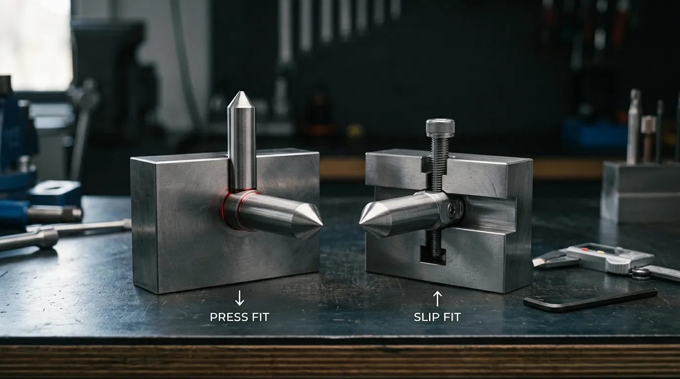
What Press Fit and Slip Fit Mean in a Punch Assembly
The fit being compared is the dimensional relationship between the punch shank and the bore in the punch plate or retainer. It is not the cutting clearance between the punch tip and die opening.
The general terminology comes from limits-and-fits systems such as ISO 286-1, but the standard does not prescribe one universal fit for punch pins. The appropriate dimensions must be chosen for the actual punch diameter, materials, plate construction, loading, assembly method, and maintenance strategy.
Press Fit: Interference Between the Punch Shank and Bore
With a press fit, the punch shank is intentionally larger than the effective mounting bore within specified limits. Installation therefore requires controlled force or another approved assembly method.
The interference can help resist relative movement between the punch and plate. It may also contribute to positional stability. However, the interference should not automatically be treated as the complete retention system. A headed punch, flange, backing plate, shoulder, or another feature may still carry part of the axial load or prevent withdrawal.
Too much interference can increase assembly force and create a risk of scoring, deformation, or dimensional change. Too little may not produce the intended engagement.
Slip Fit: Controlled Clearance With Separate Retention
A slip fit provides intentional positive clearance between the punch shank and its mounting bore. The punch can normally be inserted or removed without pressing it through the plate.
This does not mean the punch should move freely during stamping. A properly designed slip-fit arrangement uses another feature to provide positive axial retention and, where necessary, angular orientation. Depending on the tooling system, that feature may be:
- A punch head or flange
- A bolt or adjustment pin
- A key or shaped holder
- A dedicated retainer
- A ball-lock mechanism
- A separate anti-rotation feature
Ball lock is one example of a removable punch-retention system. It is not a synonym for every slip-fit punch.
Fit, Retention, Location, and Guidance Are Separate Functions
Several functions must be considered independently:
| Function | What It Controls |
|---|---|
| Fit | Clearance or interference between the punch shank and bore |
| Retention | Resistance to axial withdrawal, including stripping force |
| Location | Position of the punch axis in the die assembly |
| Orientation | Angular position of shaped or non-round punches |
| Guidance | Control of the punch near its working path |
| Backing support | Transfer of compressive punching load into the die structure |
One component may perform more than one function. For example, a punch plate may both locate and hold a press-fit punch. In another design, a retainer may hold the punch while a stripper plate guides it closer to the working end. MISUMI’s technical reference on punch and die mounting methods shows both press-fit mounting and clearance-fit arrangements with separate guidance or retention features.
Press Fit vs Slip Fit Punch Pins at a Glance
| Comparison Factor | Press Fit | Slip Fit |
| Shank-to-bore relationship | Controlled interference | Controlled clearance |
| Installation | Requires controlled pressing or another force-assisted method | Usually inserted without pressing |
| Removal | May require pressing, rear access, or partial disassembly | Normally easier if the release feature is accessible |
| Axial retention | Fit may contribute, often combined with a head or backing feature | Requires positive retention separate from the clearance |
| Positional control | Can provide firm engagement when bore geometry is correct | Depends more visibly on retainer accuracy, guiding features, and tolerance stack |
| Replacement frequency | Better suited where replacement is relatively infrequent | Often preferred where punches are changed regularly |
| Risk during repeated service | Bore or shank condition may change after repeated removal | Retainer, locking feature, and guiding surfaces must be checked for wear |
| Shaped-punch orientation | May rely on press-fit geometry plus a head, flat, or key | Usually needs a defined anti-rotation or orientation feature |
| Best-fit scenario | Stable mounting with controlled assembly access | Serviceable system with positive retention and reliable guidance |
The most important distinction is not simply “tight” versus “loose.” It is whether the complete assembly provides enough retention, location, guidance, and service access for the intended application.
How Press Fit Affects Punch Retention and Maintenance
A press fit creates contact around the punch shank and mating bore. In a well-designed assembly, this can help prevent relative movement and keep the punch firmly engaged with the mounting plate.
The working load still has to pass through the complete die structure. A punch head, shoulder, backing plate, or retainer surface may support the punch under compressive load. Stripping force acts in the opposite direction when the stock is removed from the punch, so the design must also prevent axial withdrawal.
Dayton Progress distinguishes one of its headed press-fit systems from quick-change ball-lock tooling, noting that the press-fit arrangement requires more retainer disassembly during replacement. That is useful as a system example, but it should not be treated as a rule for every press-fit punch design.
Where Press Fit Is Most Useful
Press fit may be suitable when:
- The punch is not expected to be changed frequently.
- The punch plate and bore can be manufactured and inspected consistently.
- Controlled installation and removal access are available.
- A compact mounting arrangement is preferred.
- The punch head, backing surface, and guidance system already provide the required load support.
- The mating bore is intended to remain stable through the planned service life.
The decision should still be based on the complete assembly. Production volume alone is not enough to determine the fit.
Service and Replacement Limitations
A press-fit punch may require access behind the plate, a controlled press-out operation, or removal of other retainer components. Before fitting a replacement, the maintenance team should inspect both the punch shank and the mounting bore.
Important checks include:
- Bore diameter and roundness
- Scoring, burrs, deformation, or material pickup
- Bore perpendicularity and position
- Punch-shank condition
- Head or shoulder seating
- Backing-plate contact
- Orientation of shaped punches
A replacement punch should not automatically be installed into a previously serviced bore without verification. If the bore has enlarged, become out of round, or suffered surface damage, the original fit may no longer be achieved.
How Slip Fit Affects Punch Retention and Maintenance
Slip fit makes removal easier by providing controlled clearance at the punch shank. That service advantage shifts more responsibility to the retainer, orientation feature, and guiding system.
The design must answer three questions clearly:
- What prevents the punch from pulling out?
- What controls its radial and angular position?
- What guides the punch close to the cutting area?
If those functions are defined properly, a slip-fit punch does not need to operate as a loose component.
Positive Retention Options for a Slip-Fit Punch
| Retention Feature | Main Function | Service Consideration |
| Head or flange | Prevents axial withdrawal against a backing surface | May require access to the rear of the assembly |
| Bolt or adjustment pin | Mechanically secures the punch or holder | Fastener condition and locking method must be checked |
| Key or shaped holder | Retains or orients the punch | Fit and wear of the keyway affect repeatability |
| Dedicated retainer | Locates and holds the punch as a separate assembly | Retainer mounting and dowel location become part of the tolerance chain |
| Ball lock | Provides positive retention with a release mechanism | Ball, seat, groove, orientation, and release access require inspection |
Ball-lock systems are widely used for removable tooling, but their dimensional details are product-specific. Values from one manufacturer’s catalogue should not be applied automatically to another retainer system.
Accuracy Depends on Location, Guidance, and Tolerance Stack
The presence of clearance does not by itself determine punch-point accuracy. The final position may depend on:
- Retainer-bore position
- Bore perpendicularity
- Dowel or mounting-screw location
- Punch-shank clearance
- Anti-rotation features
- Backing-plate flatness
- Punch length
- Stripper-guide clearance
- Die-opening location
A stripper-guided arrangement can control the punch closer to the working end, reducing reliance on the punch-plate fit alone. The MISUMI mounting reference illustrates this type of relationship.
Slip-fit and ball-lock systems can still accumulate positional variation across several interfaces. Dayton Lamina’s technical discussion of ball-lock tooling demonstrates why retainer clearances, mounting accuracy, and component geometry must be evaluated as a system rather than individually.
Choose the Fit by Load, Accuracy, and Changeover Needs
The choice should be made from application requirements, not from a general assumption that one fit is stronger or more precise.
| Selection Question | Press Fit May Be Favoured When | Slip Fit May Be Favoured When |
| How often is the punch replaced? | Replacement is infrequent | Replacement is routine or time-sensitive |
| Is positive retention available? | The complete press-fit, head, and backing arrangement already provides suitable retention | A dedicated retainer, head, key, bolt, or ball lock is available |
| How is the punch guided? | The punch plate or another feature provides adequate control | Guidance is provided separately, such as near the punch tip |
| Is maintenance access restricted? | Controlled pressing or disassembly remains practical | Direct removal through a release mechanism is more practical |
| Is the punch shaped or non-round? | Orientation can be controlled reliably within the mounting design | A key, flat, holder, or oriented retainer provides repeatable angular location |
| Are interchangeable spares required? | The bore and replacement shanks can maintain the intended interference | Standardised clearance and retention features support repeatable replacement |
| Is side loading expected? | The complete fit and guidance structure can resist the load | Separate close guidance can control the punch near the working area |
| Is the existing bore already worn? | Only after inspection confirms that the required interference can still be achieved | A redesigned retainer may be considered, but conversion requires engineering review |
Favour Press Fit When Retention Is Stable and Changes Are Infrequent
Press fit is more attractive when the punch is expected to remain installed for long periods, controlled assembly equipment is available, and the mating bore can maintain its specified geometry. It also suits designs where a compact arrangement is more valuable than rapid replacement.
The head, backing support, punch length, and guidance method still need separate verification.
Favour Slip Fit When Replacement and Access Drive the Design
Slip fit is more attractive when punches are changed regularly, spare interchangeability matters, or pressing the component from the plate would interrupt maintenance.
This option depends on a reliable positive-retention feature. The retainer must also control position and orientation well enough for the required die accuracy.
Use a Complete Retention System for Demanding Cases
High stripping force, shaped punches, side loading, restricted access, or tight positional requirements may call for a purpose-designed retention and guidance system. In such cases, the press or slip relationship is only one feature within the design.
The final arrangement should be reviewed at assembly level rather than selected from a generic fit chart.
What to Specify on the Punch and Plate Drawing
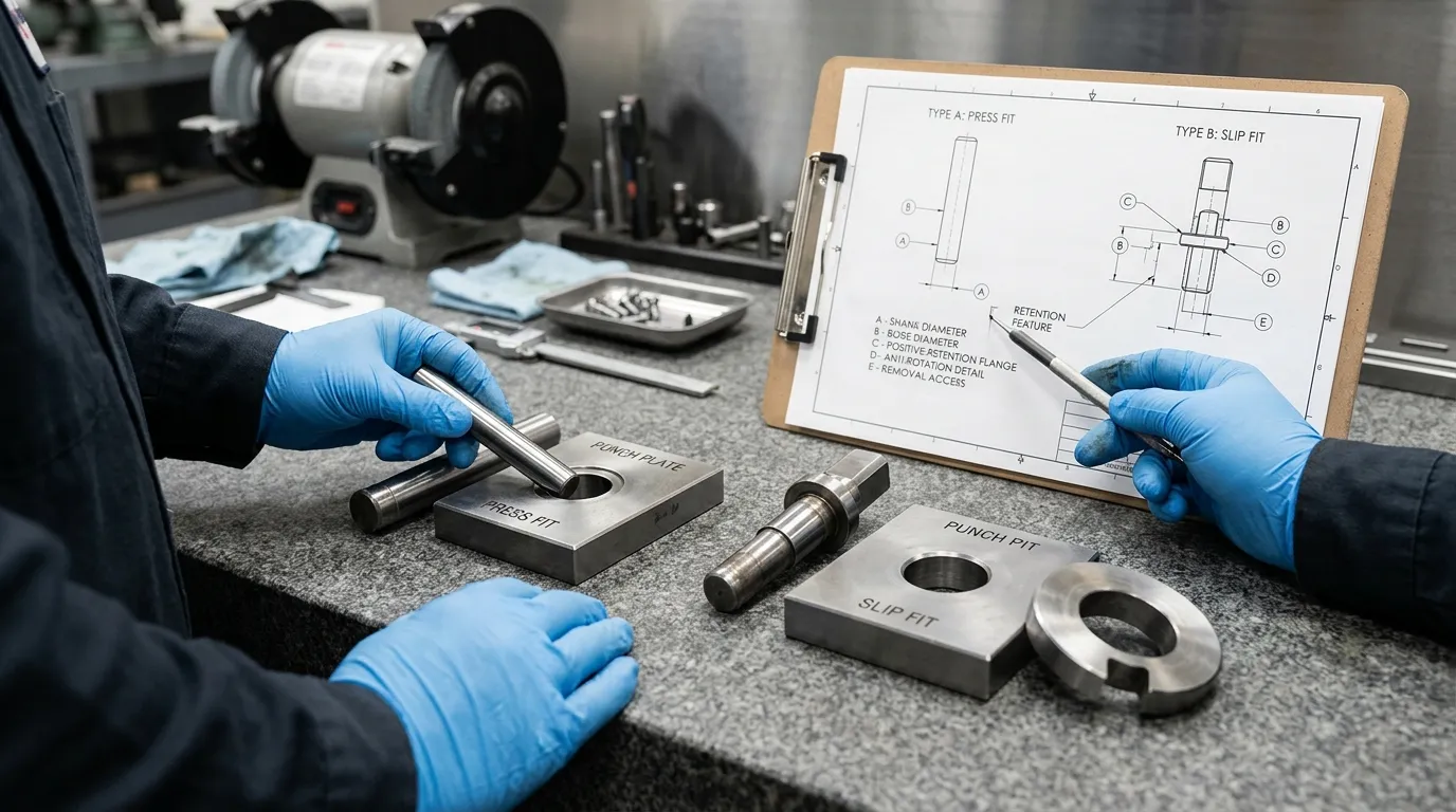
After choosing the fit concept, the drawing must define it clearly. Terms such as “tight fit” or “easy fit” are not precise enough for manufacturing or inspection.
Include the following information where relevant:
- Punch-shank nominal diameter and tolerance
- Mating-bore nominal diameter and tolerance
- Required functional clearance or interference
- Applicable fit standard and units
- Punch plate or retainer material
- Plate thickness and engagement length
- Punch head, shoulder, groove, key, or locking feature
- Anti-rotation details for shaped punches
- Bore position and perpendicularity requirements
- Relevant datums
- Backing-plate or seating requirements
- Release-tool or removal access
- Replacement and interchangeability expectations
- Inspection or gauge requirements
SunshinePro states that custom non-standard mould and die accessories can be produced from customer drawings or samples. The fit should still be defined by the customer’s die design or confirmed through an engineering review rather than inferred by the supplier from an ambiguous note.
Installation and Inspection Risks for Each Fit
Correct dimensions on a drawing do not guarantee a successful assembly if the components are dirty, damaged, misaligned, or inspected incorrectly.
Press-Fit Risks to Check
Before installation or replacement, inspect for:
- Burrs or contamination on the shank and bore
- Incorrect lead-in or damaged bore edges
- Shank or bore dimensions outside limits
- Scoring or material pickup from previous removal
- Bore enlargement or loss of roundness
- Incomplete seating against the head or backing surface
- Incorrect orientation
- Misalignment during pressing
Do not use installation force alone as proof that the correct fit has been achieved. Excessive force may indicate a dimensional, geometric, surface, or alignment problem.
Slip-Fit Risks to Check
For a slip-fit assembly, inspect:
- Clearance against the drawing limits
- Wear in the retainer bore
- Condition of the head, key, bolt, ball, groove, or holder
- Anti-rotation control
- Dowel and retainer-mounting accuracy
- Backing-plate contact
- Release access
- Signs of unintended movement
- Accumulated positional error across the retainer and guide system
Mounting problems can contribute to poor alignment or unfavourable punch loading, but they are not the only causes of failure. Material choice, heat treatment, cutting clearance, side force, and punch geometry also matter. Those wider failure mechanisms are covered in punch breakage in stamping dies.
Common Mistakes When Choosing the Punch-Pin Fit
- Treating slip fit as uncontrolled looseness. A designed clearance can operate accurately when the retainer and guidance system control the punch.
- Assuming interference is the complete retention method. The head, backing surface, stripping force, and removal direction still matter.
- Selecting from a generic fit chart only. ISO fit classes provide a dimensional framework, not an automatic punch-design answer.
- Ignoring punch guidance. A firm shank fit cannot compensate for every issue caused by punch length, side loading, or poor working-end guidance.
- Ignoring orientation. Shaped punches need a reliable anti-rotation feature.
- Failing to plan removal access. A mechanically sound fit may still create an impractical maintenance process.
- Reusing a worn bore without inspection. The replacement punch may not achieve the intended fit or position.
- Applying one ball-lock specification to every supplier. Retainer geometries and clearances are system-specific.
- Confusing mounting fit with cutting clearance. The shank-to-bore relationship is separate from the clearance between the punch tip and die opening. The broader punching dies guide covers the wider die-system context.
- Converting press fit to slip fit without redesigning retention. Increasing bore clearance changes how the punch is held, located, and guided.
What to Confirm With a Punch-Pin Supplier
Before ordering a replacement or custom punch pin, provide enough information for the supplier to understand the complete mounting arrangement:
- Punch drawing or physical sample
- Mating punch plate or retainer details
- Required press fit, slip fit, or explicit dimensional limits
- Retention and anti-rotation method
- Punch head, shoulder, groove, or locking geometry
- Required position, perpendicularity, and orientation
- Replacement and interchangeability expectations
- Inspection requirements
- Relevant application and service conditions
SunshinePro lists punching dies and pins among its product categories and accepts enquiries for standard or tailored component requirements. For a custom or replacement project, submit the punch drawing or sample together with the mating-bore, retention, orientation, and service requirements through the contact page.
Share:


Written By Tonmoy
NEWS
GET SERVICE
With quality parts to meet every budget and friendly staff trained to make your visit informative and hassle free.
