



Punch Pin Hardness Requirements Without Sacrificing Toughness
Punch pin hardness requirements cannot be reduced to one universal HRC value. Many hardened tool-steel punches are supplied in the upper-50s to low-60s HRC range, and 60–62 HRC appears frequently in commercial specifications. That does not mean every punch should be hardened to 60–62 HRC.
The correct working hardness depends on the punch material, workpiece material, sheet thickness, punch geometry, impact loading, punch–die clearance, alignment, and expected failure mode. The goal is to use enough hardness to resist wear and plastic deformation while retaining enough toughness to prevent chipping and cracking.
Hardness is only one part of the wider die-selection process. The punching dies guide (inferred) covers die types, materials, clearance, tolerances, and supplier evaluation more broadly. This guide focuses specifically on selecting and verifying punch-pin hardness.
What Hardness Should a Punch Pin Have?
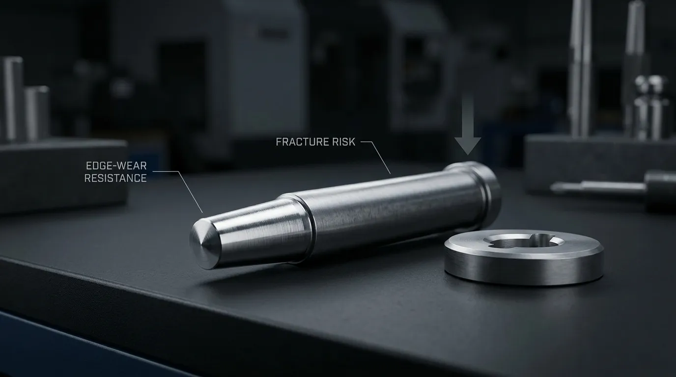
For many hardened tool-steel punch pins, a specification somewhere between approximately 58 and 64 HRC may be encountered. The suitable range, however, must be tied to a named material grade and a defined application.
A useful distinction is:
| Type of hardness value | What it means | How it should be used |
|---|---|---|
| Typical commercial range | A range commonly published for a product or punch material | Initial reference only |
| Material-datasheet recommendation | A range recommended for a particular grade, heat-treatment condition, or application | Technical starting point |
| Application-specific requirement | The acceptable range stated on the drawing or purchase specification | Manufacturing and inspection requirement |
A supplier’s published range should not automatically become the drawing requirement. For example, SunshinePro’s SKH51 punch pin page lists 60–64 HRC, while its SKH9 punch pin page lists 58–64 HRC. These are product-specific published ranges, not proof that either entire range is suitable for every stamping condition.
A drawing should normally state an acceptable range rather than an unexplained single value. Specifying “62 HRC” without a tolerance, material grade, test method, or application context leaves too much room for misunderstanding.
Why Maximum Hardness Can Shorten Punch Life
Hardness describes resistance to localized plastic deformation. A harder punch is generally less likely to indent, mushroom, or lose its cutting profile under load. Higher hardness may also reduce certain forms of wear.
That benefit has limits.
As working hardness rises, the material may become more sensitive to notches, sharp corners, grinding damage, side loading, and impact. A punch can therefore resist gradual wear but become more likely to chip or crack.
The University of Southampton’s engineering guidance on hardness also stresses that hardness is only one mechanical measurement. It cannot replace consideration of toughness and other properties.
| Property | What it helps the punch resist | What happens when it is inadequate |
| Hardness | Local indentation and plastic deformation | Mushrooming, edge deformation, loss of profile |
| Wear resistance | Material loss from the edge or face | Edge rounding, dimensional loss, frequent sharpening |
| Compressive strength | Permanent deformation under high contact stress | Crushing or plastic flow near the working end |
| Toughness and ductility | Crack initiation and propagation | Chipping, fatigue cracking, sudden fracture |
A punch material therefore needs a property balance, not simply the highest achievable HRC. Uddeholm’s tooling guidance for advanced high-strength steel explains that high hardness helps prevent plastic deformation and heavy wear but also increases brittleness and sensitivity to stress concentration.
Hardness, Toughness, Wear Resistance, and Hardenability Are Not the Same
These terms are related, but they do not describe the same behavior:
- Hardness is resistance to localized plastic deformation, usually reported for hardened punch pins on the Rockwell C scale.
- Toughness is the ability to resist fracture and absorb mechanical loading without cracking.
- Ductility affects how well a material can deform locally before fracture.
- Wear resistance describes resistance to material loss. It depends on hardness, carbide structure, workpiece material, friction, lubrication, and surface condition.
- Hardenability is the ability of a steel to develop hardness through its cross-section during heat treatment. It is not the final HRC reading.
Two punches can measure the same HRC and still perform differently because their carbide distribution, microstructure, heat-treatment quality, residual stress, and toughness are different.
What Determines the Correct Working-Hardness Range?
A credible punch-pin hardness requirement starts with the material grade and then accounts for the real cutting conditions.
Use the following sequence:
- Confirm the punch material and its validated heat-treatment window.
- Assess the workpiece material, strength, thickness, and wear behavior.
- Review punch diameter, length, profile, corners, and unsupported section.
- Check impact loading, press speed, and production conditions.
- Verify punch–die clearance and alignment.
- Identify the dominant failure mode that must be controlled.
- Define the hardness range, test method, and documentation requirements.
Start With the Material’s Validated Heat-Treatment Window
Each tool-steel family has a different balance of wear resistance, compressive strength, dimensional stability, and fracture resistance.
A D2- or SKD11-type cold-work steel may offer strong abrasive-wear resistance, but it should not be treated as mechanically identical to an A2-type steel, high-speed steel, shock-resistant steel, or powder-metallurgy grade at the same HRC.
The selected hardness must remain within a range supported by the material supplier’s technical data and the intended heat-treatment condition. Forcing a steel to its maximum attainable hardness can reduce the safety margin against chipping without solving the actual wear mechanism.
Heat treatment also affects more than the final HRC reading. Austenitizing, quenching, and tempering establish the microstructure, carbide condition, residual stress, and dimensional stability of the punch. A correct nominal HRC cannot compensate for poor heat-treatment control.
Adjust for Workpiece Material and Sheet Thickness
The workpiece changes both the cutting load and the dominant wear mechanism.
Hard, abrasive sheet can accelerate edge wear. Stronger or thicker sheet generally increases cutting force and may increase the need for toughness and compressive strength. Softer but adhesive materials can cause galling or material pickup, which may not be corrected by raising core hardness.
Grade-specific recommendations can change with thickness. Uddeholm’s Rigor technical data, for an A2-type cold-work steel, gives the following cutting guidance:
| Workpiece thickness | Recommended hardness for this specific grade |
| Up to 3 mm | 60–62 HRC |
| 3–6 mm | 56–60 HRC |
| 6–10 mm | 54–56 HRC |
These figures apply to that material and the conditions covered by the manufacturer’s guidance. They should not be transferred automatically to SKH51, SKH9, D2, carbide, or another punch material.
The important lesson is that the “best” hardness can decrease as the mechanical demand shifts from edge-wear resistance toward toughness.
Account for Punch Geometry, Clearance, and Alignment
Small-diameter and slender punches are more sensitive to bending and side loading than short, heavily supported punches. Sharp internal corners, narrow sections, notches, and abrupt profile changes also concentrate stress.
In these cases, increasing hardness can reduce the material’s ability to tolerate the concentrated load.
Punch–die clearance is equally important. A peer-reviewed study of punch hardness and die clearance found that both variables influenced tool wear and cut quality under the tested conditions. That does not provide a universal hardness formula, but it confirms that hardness cannot be evaluated independently of clearance.
Misalignment can create uneven contact and side loading even when the hardness specification is correct. Worn guide components, poor concentricity, or off-center punch entry can produce chipping that appears to be a material problem. The die components guide explains the broader relationship between guiding components, alignment, wear, and die performance.
Select Hardness by the Failure Mode You Need to Prevent
The observed failure mode can indicate which property deserves greater attention. It should not be used as proof that hardness alone is wrong.
| Observed condition | Possible hardness-related explanation | Other causes to check | Likely corrective direction |
| Gradual edge rounding or face wear | Insufficient wear resistance for the application | Abrasive workpiece, poor clearance, unsuitable carbide structure, rough surface | Review material grade, clearance, heat treatment, and surface treatment |
| Mushrooming or plastic deformation | Hardness or compressive strength may be too low | Excessive load, weak section, wrong grade | Review load, material, geometry, and working hardness |
| Edge chipping | Hardness may be too high for the available toughness | Sharp corners, misalignment, poor clearance, grinding damage, impact | Improve geometry and alignment; review toughness and HRC |
| Fatigue cracking or sudden fracture | Insufficient fracture resistance or excessive notch sensitivity | Side loading, repeated impact, heat-treatment defects, surface damage | Investigate the complete loading and manufacturing history |
| Galling or material pickup | Higher HRC may not address the main mechanism | Adhesive work material, poor lubrication, high friction, unsuitable coating | Review lubrication, surface finish, substrate, and coating |
A worn punch is not automatically too soft. A chipped punch is not automatically too hard.
Before changing the HRC requirement, determine whether the problem is abrasive wear, adhesive wear, plastic deformation, impact fracture, fatigue cracking, or misalignment. Broader mechanical causes are covered in punch breakage in stamping dies.
Core Hardness and Surface Hardness Serve Different Purposes
Core hardness describes the condition of the punch substrate. It affects load-bearing capacity, deformation resistance, and fracture behavior.
Surface treatments serve a different purpose.
Nitriding can create a hard surface layer over a heat-treated core. PVD or CVD coatings can modify friction, adhesion, and surface-wear behavior. A coated punch can therefore have:
- One core-hardness requirement.
- A separate surface-treatment specification.
- Different surface and substrate properties.
| Requirement | Primary function |
| Core hardness | Supports the punch under load and contributes to deformation and fracture resistance |
| Nitrided layer | Improves surface hardness and wear behavior over a controlled depth |
| PVD or CVD coating | Changes friction, adhesion, and surface-wear conditions |
A hard coating cannot correct poor alignment, inadequate substrate support, sharp stress concentrations, or an unsuitable material grade. Coating performance also depends on the substrate condition and surface preparation.
Uddeholm’s Vanadis 4 Extra technical data discusses nitriding and PVD/CVD treatments in relation to a properly heat-treated tool-steel substrate.
On a drawing, state the core heat-treatment requirement and the surface treatment separately. Do not use one hardness number to describe both.
How to Specify Punch-Pin Hardness on a Drawing or RFQ
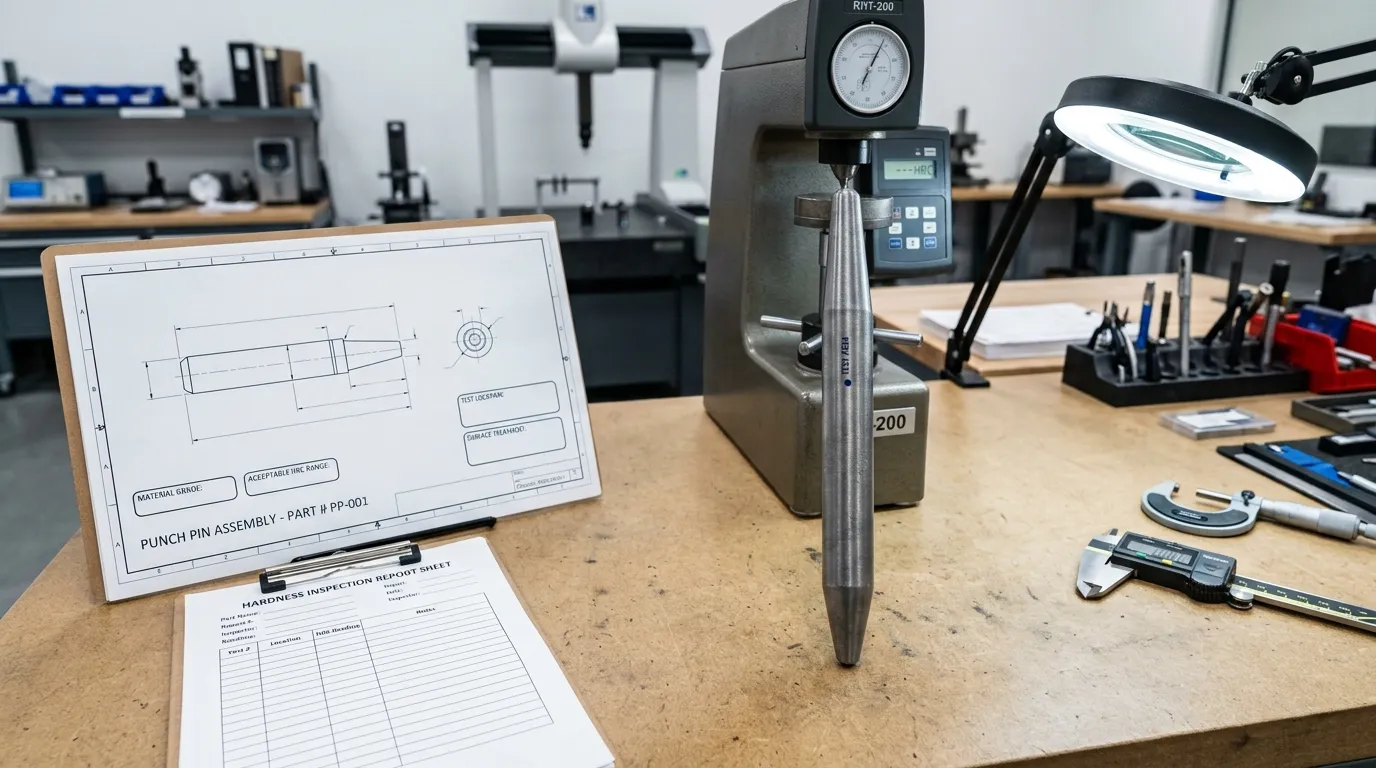
A useful hardness note needs enough information for manufacturing and inspection. “High hardness” or “maximum hardness” is not an adequate requirement.
Include:
- Material grade
State the exact steel grade or permitted equivalent. - Final heat-treated condition
Make clear that the hardness applies after the required heat treatment. - Acceptable hardness range
Use a controlled range supported by the material and application. - Hardness scale
State HRC or another appropriate scale explicitly. - Test method
Reference a recognized method when contractual verification is required. - Test location
Identify the measurement area where practical and technically suitable. - Sampling requirement
Define whether readings are required per part, per batch, or under an agreed inspection plan. - Surface treatment
List coating, nitriding, or other treatment separately from core hardness. - Application information
Give the workpiece material, thickness, punch geometry, clearance, speed, and expected loading. - Required documentation
State whether a material certificate, heat-treatment record, or hardness inspection report is needed.
Define the Range, Scale, Method, and Test Location
ASTM E18-25 provides requirements for Rockwell hardness testing of metallic materials. It also warns that a hardness result represents the material condition at the test location and may not represent the complete part.
ISO 6508-1:2023 covers regular and superficial Rockwell hardness testing for metallic materials.
The drawing or purchase specification should therefore avoid ambiguous notes such as:
- “Hardness: 62.”
- “Maximum hardness.”
- “Very hard.”
- “Same hardness as standard punch.”
A clearer specification structure is:
Material grade + final heat-treatment condition + acceptable HRC range + test method + agreed test location + required inspection documentation.
The actual range must come from the selected material, geometry, and application. It should not be copied from a general example.
Small diameters, curved surfaces, thin sections, and surface-treated areas may require review of the test method and location. A standard Rockwell indentation may not be appropriate in every position.
Request the Documents Needed to Verify the Final Condition
Depending on the order and criticality, the buyer may request:
- Material certificate or grade verification.
- Heat-treatment record.
- Hardness inspection report.
- Reported readings and hardness scale.
- Test method and measurement location.
- Production-lot identification.
- Separate coating or nitriding documentation.
These records confirm material identity and measured condition. They do not guarantee a fixed number of stamping cycles because tool life also depends on geometry, clearance, alignment, lubrication, workpiece variation, and operating load.
SunshinePro’s Published SKH51 and SKH9 Hardness Ranges
SunshinePro publishes different hardness ranges for two HSS punch-pin products:
| Product | Published material | Published hardness | Listed processing |
| SKH51 punch pin | JIS SKH51 / HSS | 60–64 HRC | Vacuum heat treatment, CNC machining, precision grinding |
| SKH9 punch pin | JIS SKH9 / HSS | 58–64 HRC | Vacuum heat treatment, CNC machining and grinding |
The pages also describe custom dimensions and optional surface treatments.
These values should be treated as SunshinePro’s published product specifications. They are not universal recommendations for all SKH51 or SKH9 applications, and they do not replace review of the workpiece, sheet thickness, punch shape, clearance, alignment, and failure risk.
Before Changing HRC, Check the Rest of the Punching System
A correctly hardened punch can still fail early if another part of the system is wrong.
Before increasing or decreasing hardness, check:
- Punch–die clearance.
- Punch and die alignment.
- Guide-post and bushing condition.
- Side loading or off-center entry.
- Unsupported punch length.
- Sharp corners and narrow sections.
- Workpiece material variation.
- Lubrication and material pickup.
- Grinding or EDM surface damage.
- Heat-treatment distortion.
- Whether the observed failure is wear, deformation, chipping, galling, or fatigue.
Correcting alignment or geometry may solve a breakage problem without changing hardness. A coating or lubrication change may solve galling more effectively than raising core HRC.
Information to Provide for a Punch-Hardness Review
A supplier cannot make a credible hardness recommendation from the punch diameter alone.
Provide:
- Punch drawing and critical dimensions.
- Preferred material or approved alternatives.
- Workpiece material and condition.
- Sheet thickness.
- Punch length, diameter, and profile.
- Punch–die clearance.
- Press speed and operating load.
- Current wear or failure pattern.
- Required core-hardness range.
- Coating or nitriding requirements.
- Inspection and documentation expectations.
SunshinePro states that it supplies standard mold components and processes non-standard parts from customer drawings. For an application-specific review, send the relevant drawing and operating details through the contact page. The requested HRC range should then be evaluated as part of the complete material, geometry, loading, and surface-treatment specification.
Frequently Asked Questions
Should the punch and die have the same hardness?
Not necessarily. The punch and die have different geometries, loading conditions, support, wear patterns, and failure risks. Each component should be specified according to its material and function rather than matched automatically to the same HRC.
Can a punch pin be too hard?
Yes. Excessive working hardness can reduce the margin against chipping, cracking, and notch-sensitive failure. The risk is greater with slender punches, sharp corners, impact loading, poor alignment, or inadequate clearance.
Does a higher HRC guarantee longer punch life?
No. HRC measures indentation hardness at the test location. It does not measure toughness, coating adhesion, alignment, clearance, surface integrity, or the complete wear mechanism. A harder punch can wear more slowly in one application and fracture earlier in another.
How many hardness readings should be taken?
There is no universal sampling number for every punch size and order. The inspection plan should account for part geometry, production quantity, application criticality, test accessibility, and the buyer–supplier agreement. The drawing or purchase specification should state the expected sampling and reporting method.
Share:


Written By Tonmoy
NEWS
GET SERVICE
With quality parts to meet every budget and friendly staff trained to make your visit informative and hassle free.
