



Punch Pins for Fine Blanking: Clearance, Finish, and Edge Quality
Punch pins for fine blanking cannot be selected by hardness, coating, or nominal diameter alone. Edge quality depends on how the punch works with the die, blankholder, V-ring, counterpunch, work material, lubrication, and press alignment. Very small clearance makes the process especially sensitive to profile error, edge wear, surface damage, and side loading.
This guide focuses on those fineblanking-specific requirements. For broader information about die types, tooling materials, and general purchasing considerations, see the punching dies guide (inferred).
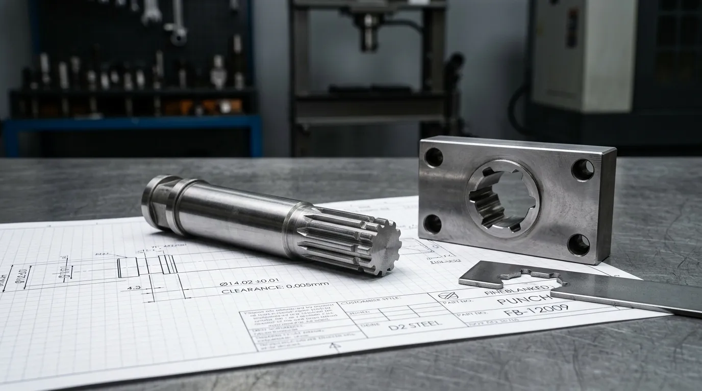
Why Fineblanking Punches Need a System-Level Specification
Fineblanking produces a high proportion of controlled shear by restraining the sheet before and during cutting. The blankholder clamps the material, a V-ring or impingement ring limits lateral flow, and the counterpunch applies pressure from the opposite side. The punch and die then separate the material through a very small clearance.
This system changes the stress state around the cutting line. It can reduce the fracture zone and improve edge perpendicularity compared with conventional blanking, but it also makes tooling errors more visible. A punch that is dimensionally correct on its own may still perform poorly if the guide fit, die position, counterpressure, or material condition creates uneven local clearance.
A peer-reviewed fineblanking study describes the interaction among clearance, V-ring geometry, counterpressure, cutting-edge preparation, and material flow. This relationship is why a fineblanking punch should be specified as one part of a matched system.
Distinguish the Blanking Punch, Piercing Punch, and Generic Punch Pin
“Punch pin” is a broad product term. In a fineblanking application, the drawing should identify the actual cutting function.
| Tooling term | Function | Dimension it commonly controls |
|---|---|---|
| Blanking punch | Cuts the external profile of the retained part | Works with a die opening that controls the finished blank size |
| Piercing punch | Produces an internal hole or opening | Commonly controls the finished hole size |
| Punch pin | General term that may describe either function | Must be clarified on the drawing or RFQ |
This distinction matters because the punch and die are not dimensioned or edge-prepared in the same way for external blanking and internal piercing.
Using only “punch pin” on an RFQ leaves several questions unanswered:
- Is the finished feature an external blank or an internal hole?
- Which member controls the finished dimension?
- Which cutting edge must remain sharp?
- Where is the intended radius or edge preparation?
- Is the punch guided through a plate?
- How is clearance defined?
These details affect the punch profile, die opening, inspection method, and regrinding plan.
Match Cutting-Edge Preparation to Blanking or Piercing
For standard external fineblanking, the punch cutting edge is generally kept sharp while the corresponding die edge is prepared with a controlled radius. In piercing, the relationship is reversed: the piercing punch receives the relevant edge preparation while the die edge remains sharp.
This blanking-versus-piercing distinction is supported by fineblanking research and should be shown explicitly on the tool drawing. It should not be left to a generic note such as “break all sharp edges.”
Uncontrolled polishing can be just as harmful as an incorrect radius. Polishing the cutting edge may:
- Round an edge that should remain sharp.
- Change the effective punch profile.
- Increase local clearance.
- Produce inconsistent edge preparation around corners.
- Remove a coating from a critical area.
- Hide grinding damage without correcting the underlying geometry.
Edge preparation should therefore be specified by location and function. The punch face, flank, guide surface, and cutting edge do not necessarily require the same treatment.
Set Clearance by Material, Geometry, and Edge Requirement
Fineblanking uses much smaller punch–die clearance than conventional blanking. Small clearance supports a larger clean-shear zone, but it also increases cutting force, friction, heat, and sensitivity to alignment.
Some technical literature cites clearance around 0.5% of sheet thickness as a basic fineblanking guideline. The same research warns that this value must be adapted to the geometry and application. It is a starting point for engineering evaluation, not a universal production specification.
The final clearance decision should account for:
- Material grade and condition.
- Sheet thickness and thickness tolerance.
- Hardness, tensile strength, and ductility.
- Microstructure and rolling direction.
- Part profile and corner geometry.
- Required clean-shear depth.
- Allowed fracture zone and burr height.
- V-ring and counterpunch forces.
- Punch and die rigidity.
- Lubrication.
- Tool material and cutting-edge condition.
- Expected wear during the production run.
Clearance should be validated against the assembled tool and actual work material. A punch supplier cannot establish finished edge quality from the punch drawing alone if the die, guide system, force settings, and material condition are unknown.
Specify Per-Side, Total, and Relative Clearance Correctly
A drawing should state whether the listed clearance is per side or total.
For a symmetrical profile:
- Per-side clearance, c: gap between the punch and die on one side.
- Total clearance: combined clearance across both sides, normally 2c.
- Relative clearance: per-side or total clearance expressed as a percentage of sheet thickness. The convention must be stated.
For example, if the per-side clearance is shown as 0.01 mm, the total diametral difference between a round punch and die opening is 0.02 mm. This is only a dimensional illustration, not a recommended fineblanking value.
The controlling dimension also changes with the operation:
- In external blanking, the die opening normally controls the retained blank profile. The punch is smaller by the total clearance.
- In piercing, the punch normally controls the hole profile. The die opening is larger by the total clearance.
A complete drawing should identify:
- Whether the operation is blanking or piercing.
- The finished feature dimension.
- The punch dimension.
- The die dimension.
- Whether clearance is per side or total.
- The relevant datums and geometric tolerances.
Without these details, two suppliers may interpret the same clearance note differently.
Diagnose Clearance That Is Too Small, Too Large, or Uneven
| Clearance condition | Likely edge or tooling effect | Checks before changing the nominal value |
| Too large | Earlier fracture, wider fracture zone, increased taper, larger burr, reduced clean shear | Punch and die wear, material thickness, edge condition, actual assembled dimensions |
| Too small | Higher cutting load, heat, friction, galling, accelerated wear, chipping sensitivity | Force settings, lubrication, alignment, punch toughness, corner geometry |
| Uneven around the profile | One-sided burr, local fracture, side loading, asymmetric wear, edge chipping | Punch straightness, die alignment, guide condition, holder fit, profile accuracy |
Uneven clearance is often more damaging than a slightly imperfect nominal value. A drawing may specify the correct average gap while the assembled tool produces a smaller gap on one side and a larger gap on the other.
Possible causes include:
- Punch straightness error.
- Worn guide plate or bushing.
- Incorrect shank or holder fit.
- Misaligned die inserts.
- Profile error after regrinding.
- Press or die-set deflection.
- Material feeding at an angle.
- Local coating buildup or damage.
The die components guide provides broader context on guide systems, wear parts, and component alignment. In a fineblanking tool, those components directly influence the clearance that exists under load.
Specify Punch Finish and Geometry Without Damaging the Cutting Edge
A single surface-roughness value does not fully define a fineblanking punch. The punch face, flank, cutting edge, guide surface, shank, and transition features perform different functions.
The flank slides against the work material and may be exposed to pickup, scoring, and adhesive wear. The guide surface controls positioning and side load. The cutting edge defines the start of material separation. A finish requirement should identify the exact surface and its purpose.
Average roughness, or Ra, is useful, but it can hide isolated deep scratches. Two surfaces with similar Ra values may behave differently if one contains directional grinding marks, torn material, pits, or high peak-to-valley variation.
Where the application is sensitive, the specification may also address:
- Rz, Rt, or another peak-to-valley parameter.
- Measurement direction.
- Measurement location.
- Sampling length and cutoff.
- Maximum scratch depth.
- Visual or optical acceptance criteria.
- Grinding-burn inspection.
- EDM recast-layer removal.
- Coating condition at the cutting edge.
Control the Face, Flank, Guide Surface, and Cutting Edge Separately
| Punch area | Main function | Main risks |
| Cutting edge | Initiates and controls shearing | Rounding, chipping, incorrect radius, coating buildup |
| Flank | Slides past the work material | Galling, pickup, scoring, abrasive wear |
| Punch face | Transfers cutting load | Chipping, deformation, grinding damage |
| Guide surface | Controls position and side load | Excessive clearance, seizure, uneven contact |
| Shank and transitions | Connect punch to the holder | Stress concentration, poor fit, bending |
Polishing is useful only when it improves the intended surface without changing geometry. An operator should not polish across a critical edge or remove material until the surface “looks smooth.” The process should preserve profile size, straightness, edge condition, and fit.
Grinding direction also matters. Deep transverse marks on a sliding flank can increase resistance and create locations for material pickup. Fine longitudinal finishing may be more appropriate on a guided or sliding surface, provided it does not alter the punch dimensions.
Verify Profile Accuracy, Straightness, Concentricity, and Runout
Very small nominal clearance requires accurate geometry throughout the punch assembly.
Profile accuracy controls local clearance around complex shapes. A small profile error near a corner can create excessive pressure even if the main dimensions are correct.
Straightness affects how the punch passes through the guide and enters the die. A long punch with slight bow may contact one side of the guide, producing side load and uneven clearance.
Concentricity or coaxiality matters for round, stepped, or multi-diameter punches. It defines how one cylindrical feature relates to another datum axis.
Runout is a practical inspection result obtained during rotation. It can reveal eccentricity, surface error, or setup error, but it should not be treated as identical to concentricity.
The inspection plan should also account for:
- Shank diameter and fit.
- Holder pocket condition.
- Guide-plate clearance.
- Punch protrusion and length.
- Die-insert location.
- Datum selection.
- Regrinding effects.
- Coating thickness on controlled surfaces.
A punch can meet its standalone dimensions and still produce poor results if the assembled tolerance stack shifts the cutting profile.
Choose Punch Material and Coating by the Dominant Failure Mode
The best punch material depends on how the tool is expected to fail. Hardness alone is not a sufficient selection criterion.
Relevant failure modes include:
- Abrasive wear from hard particles or abrasive stock.
- Adhesive wear and galling.
- Edge chipping.
- Gross fracture.
- Plastic deformation.
- Bending or side loading.
- Thermal damage.
- Coating delamination.
The work material, thickness, feature size, corner geometry, punch slenderness, guide condition, lubrication, and production volume all affect the choice.
Compare Steel and Carbide Without Declaring a Universal Winner
| Material option | Potential advantages | Main limitations | Suitable consideration |
| HSS or tool steel | Toughness, edge stability, easier regrinding, better tolerance of impact or slight misalignment | May wear faster in highly abrasive applications | Complex geometry, slender punches, applications with chipping or impact risk |
| Powder-metallurgy tool steel | Balanced wear resistance and toughness | Higher cost and material-specific heat-treatment requirements | Applications needing more wear resistance than conventional steel without full carbide brittleness |
| Tungsten carbide | High compressive strength and wear resistance | Greater sensitivity to tensile stress, impact, edge defects, and misalignment | Rigid, well-guided applications dominated by abrasive wear |
Carbide is not automatically the best choice for every fineblanking punch. A highly wear-resistant carbide punch can chip quickly if the guide system introduces side loading or if a sharp internal corner concentrates stress. A tougher HSS or tool-steel punch may provide more stable service in that condition.
SunshinePro lists HSS grades and carbide among its general punch options. Readers comparing available products can review its high-speed steel punches and carbide punch options. The application still requires confirmation against the actual work material, geometry, clearance, and expected failure mode.
Treat Coatings and Lubrication as Supporting Controls
SunshinePro lists TiN, TiCN, and DLC among coating options on relevant punch product pages. These coatings may change friction, adhesive-wear behavior, or abrasive-wear resistance, but they do not correct a poor base design.
A coating cannot fix:
- Excessive or uneven clearance.
- Incorrect edge preparation.
- A bent or misaligned punch.
- Inadequate substrate toughness.
- Poor guide fit.
- Unsupported corner geometry.
- Insufficient lubrication.
- Grinding damage beneath the coating.
Coating thickness also matters when the clearance is extremely small. A coating applied to a controlled profile or guide surface may alter the final dimension if the drawing and grinding allowance do not account for it.
Coating selection should specify the substrate, heat-treatment condition, coated surfaces, excluded surfaces, final dimensions, edge treatment, and inspection method.
Read the Fineblanked Edge to Diagnose Punch and Process Problems
The finished cut edge is a record of how the punch, die, work material, forces, lubrication, and wear interacted during the stroke.
A fineblanked edge may contain:
- Die roll or rollover: rounded deformation near the entry side.
- Clean-shear or burnished zone: smoother area produced by controlled shearing.
- Fracture zone: rougher area where material separation changes from shear to fracture.
- Burr: projection at the exit side.
- Taper: deviation from a perpendicular cut surface.
The VDI 2906 Part 5 standard provides terminology and characteristic values for evaluating fineblanked cut faces. Formal acceptance criteria should be based on the applicable drawing and standard rather than an undefined requirement such as “smooth edge.”
Measure Die Roll, Clean Shear, Fracture, Burr, and Perpendicularity
Inspection should cover more than one cross-section. Edge quality can vary around corners, narrow webs, changes in profile direction, and areas affected by material rolling direction.
A practical inspection record may include:
- Measurement position.
- Material grade and lot.
- Sheet thickness.
- Tool identification.
- Stroke count.
- Punch condition.
- Die-roll width or depth.
- Clean-shear depth.
- Fracture-zone depth.
- Burr height.
- Edge taper or perpendicularity.
- Photographs at controlled magnification.
Trend data is often more useful than a single measurement. A gradual increase in burr or fracture-zone depth may indicate progressive edge wear. A sudden one-sided defect is more likely to suggest chipping, misalignment, guide damage, or material-positioning error.
Use a Defect-to-Cause-to-Check-to-Correction Matrix
| Observed condition | Possible causes | Checks | Correction direction |
| Fracture zone becomes deeper | Excess clearance, worn edge, changed material condition, inadequate material restraint | Measure punch and die, inspect edge, verify material and force settings | Restore geometry, review clearance, confirm material and force conditions |
| Burr increases gradually | Edge rounding, abrasive wear, die wear | Compare against earlier parts, inspect edge under magnification | Regrind or replace affected tooling after confirming remaining allowance |
| Burr is larger on one side | Uneven clearance, punch bow, guide wear, die misalignment | Check straightness, guide contact, holder fit, die position | Correct alignment or worn components before changing nominal clearance |
| Material sticks to the flank | Galling, insufficient lubrication, rough surface, incompatible coating or substrate | Inspect pickup, finish, lubrication delivery, temperature | Clean and restore surface, correct lubrication, review material/coating system |
| Local edge chipping | Brittle substrate, overload, small clearance, impact, side load, grinding damage | Inspect fracture location, alignment, corner geometry, heat-treatment condition | Remove root cause and select a suitable toughness/wear balance |
| Finished profile drifts | Wear, deformation, loose holder fit, guide damage, thermal change | Check punch profile, shank fit, guide, die, and measurement setup | Restore the controlling component and revalidate clearance |
These are investigation paths, not automatic diagnoses. Several conditions can create the same visible defect.
For broader analysis of fracture, bending, and fatigue-related failures, see punch breakage in stamping dies.
Prepare the Drawing, Inspection Plan, and RFQ Before Ordering
A useful fineblanking punch inquiry needs more than a part number and nominal diameter. The supplier must understand the finished feature, work material, mating tool, quality target, and inspection method.
Include the Application Data That Controls Punch Design
Provide the following information where applicable:
- Finished-part drawing and critical dimensions.
- Identification of blanking or piercing.
- Work-material grade and condition.
- Sheet thickness and tolerance.
- Material hardness or tensile range.
- Coating or plated condition of the stock.
- Rolling direction when relevant.
- Required die roll, clean-shear depth, fracture limit, burr limit, and perpendicularity.
- Punch and die dimensions.
- Per-side or total clearance convention.
- Punch material and hardness requirement.
- Cutting-edge condition and specified radius.
- Flank and guide-surface finish.
- Straightness, concentricity, coaxiality, and runout requirements.
- Shank, holder, and guide interfaces.
- Coating type and coated surfaces.
- Regrinding allowance.
- Expected production environment.
- Existing defect photographs or samples when troubleshooting.
The RFQ should also identify which dimensions are final after coating and which surfaces must remain uncoated.
Request Evidence for Material, Hardness, Geometry, and Finish
Depending on the part risk and quality requirements, request appropriate documentation such as:
- Material certificate or traceability record.
- Heat-treatment record.
- Hardness result and test method.
- Dimensional inspection report.
- Profile measurement.
- Straightness and runout results.
- Surface-roughness measurement, including location and direction.
- Cutting-edge visual or optical inspection.
- Coating specification and application record.
Some requirements can be verified on the loose punch. Others can only be validated after assembly with the die, guide system, blankholder, and counterpunch.
The purchase specification should separate those two responsibilities clearly.
Match SunshinePro’s Verified Capabilities to the Fineblanking Specification
SunshinePro states that it supplies punching dies and pins and can manufacture non-standard mold accessories from customer drawings or samples. Its relevant product pages list HSS, tool-steel, and carbide options, along with processes such as CNC machining, precision grinding, EDM on applicable products, and vacuum heat treatment on applicable punch products.
The company website also states general punch-and-pin capability of Ra 0.4 surface finish and dimensional tolerances within ±0.002 mm. These are general capability statements. They should not be treated as proof that the same values are suitable for every fineblanking application or that they guarantee a specific cut-edge result.
A technical inquiry should ask SunshinePro to confirm:
| Verified general capability | Application detail requiring confirmation |
| Custom manufacturing from drawings or samples | Whether the submitted blanking or piercing geometry is feasible |
| HSS, tool-steel, and carbide punch options | Which substrate fits the expected wear and chipping risks |
| Precision grinding and applicable EDM processes | How the final profile, edge, and recast condition will be controlled |
| Selected coating options | Coating suitability, thickness allowance, and coated surfaces |
| General Ra and tolerance capability | Actual finish, profile, straightness, and inspection requirements for the application |
Prepare the finished-part drawing, work-material data, clearance definition, mating die information, edge-quality criteria, and inspection requirements before requesting a quotation. You can then submit the punch specification for review and ask for confirmation of material, geometry, finish, coating, and inspection feasibility.
Share:


Written By Tonmoy
NEWS
GET SERVICE
With quality parts to meet every budget and friendly staff trained to make your visit informative and hassle free.
