



Tablet Capping Tooling Solutions: Dies, Head Flats, and Dwell
Tablet capping tooling solutions can help when crown separation is linked to insufficient consolidation time, trapped air, worn dies, excessive die-wall friction, or ejection stress. They will not correct every capping problem. Poor formulation bonding, inappropriate lubrication, moisture variation, excessive fines, or unsuitable compression settings may produce the same visible defect.
Punches and dies are part of a wider system of tablet press tooling types, but this guide focuses only on tooling decisions related to capping. The objective is to prove the likely failure mechanism before changing a die, extending a punch head flat, or adjusting the compression cycle.
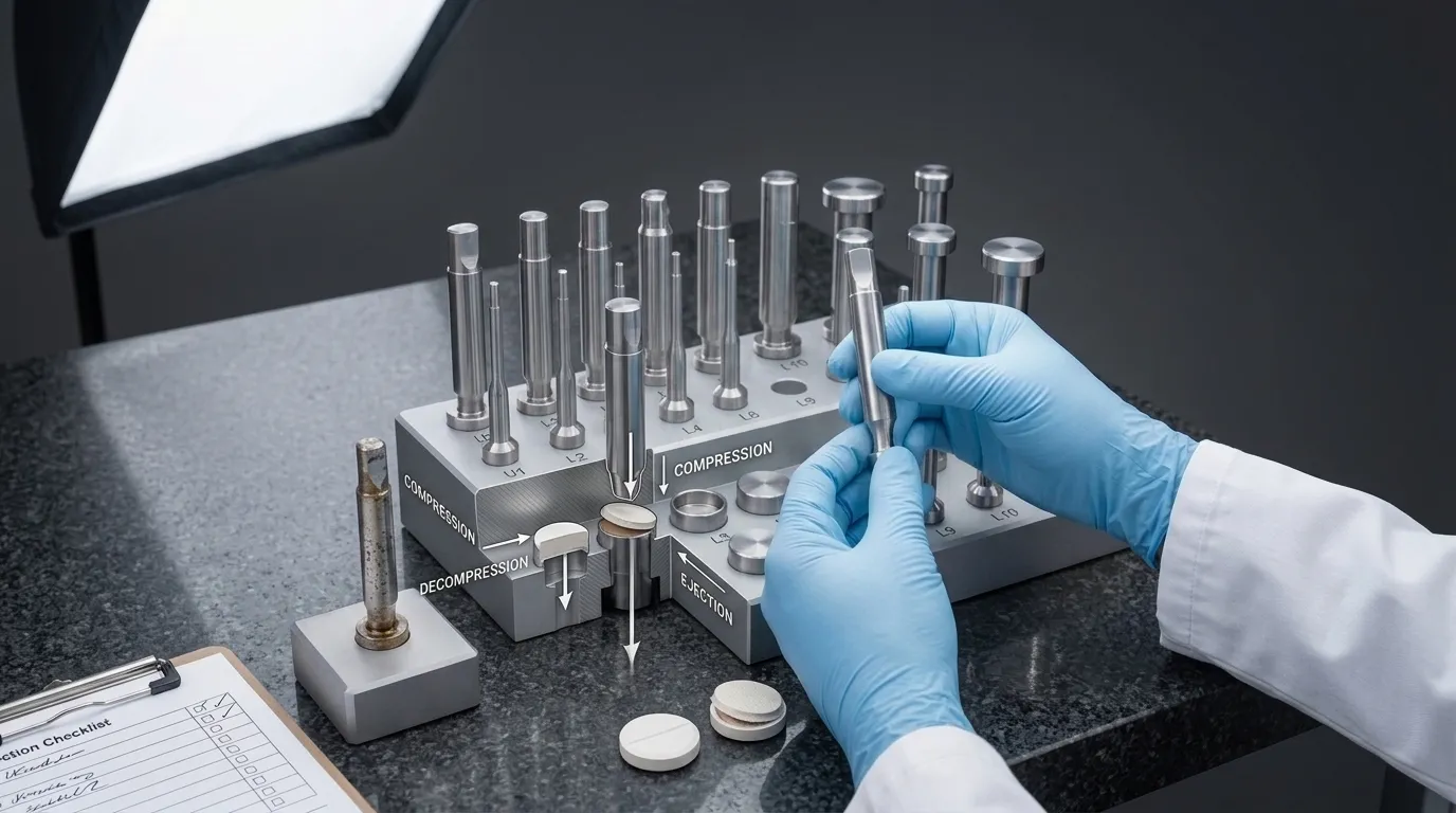
Confirm the Defect Before Changing the Tooling
Capping occurs when the upper or lower crown separates horizontally from the main tablet body. The separation may become visible during decompression, ejection, dedusting, handling, packaging, or mechanical testing.
It must first be distinguished from other defects that need different corrective actions.
| Observed defect | Typical appearance | Initial investigation |
|---|---|---|
| Capping | The top or bottom crown separates from the tablet body | Consolidation, trapped air, decompression, punch geometry, die condition, and ejection |
| Lamination | The tablet separates into two or more horizontal layers | Air entrapment, formulation properties, compression profile, and elastic recovery |
| Chipping | Small pieces break from the tablet edge | Cup or land geometry, handling, tooling damage, granulation, and tablet strength |
| Cracking | Visible cracks form without complete crown separation | Stress distribution, deep cups, formulation elasticity, and compression conditions |
| Picking | Material sticks to the punch face and is removed from the tablet surface | Punch-face condition, formulation adhesion, moisture, embossing, and lubrication |
Document exactly when and where the defect occurs. Record whether it affects:
- the upper crown, lower crown, or both;
- every tooling station or only selected stations;
- low-speed and high-speed production equally;
- tablets immediately after compression or only after handling;
- a complete batch or intermittent production periods.
A defect concentrated at one or two tooling stations is more likely to involve local punch or die condition than a defect occurring uniformly across the turret. Uniform capping across all stations may still involve tooling design, but formulation and process variables require equal attention.
Decide Whether the Root Cause Is Formulation, Process, Press, or Tooling
“Improper tooling” is not a complete diagnosis. Before ordering modified punches or dies, separate four possible source groups.
Formulation-related evidence may include poor tabletability, weak binder performance, excessive elastic recovery, inconsistent moisture, unsuitable particle-size distribution, high fines content, or excessive lubrication. A formulation that cannot develop adequate interparticle bonds may continue to cap even when dwell is increased.
Process-related evidence may include ineffective precompression, a rapid loading profile, unsuitable main-compression conditions, inconsistent die fill, or changing feed behaviour. Simply increasing compression force may make capping worse if the formulation experiences excessive elastic recovery after unloading.
Press-related evidence may appear during scale-up. A formulation may run successfully on a development press but fail on a production rotary press because punch velocity, turret geometry, compression-roller geometry, and available dwell differ.
Tooling-related evidence includes die-bore wear, scoring, abnormal clearance, damaged punch features, local contamination, unusually high ejection resistance, or a defect limited to specific stations.
The investigation should ask a simple question: What changed when the capping changed? If the defect follows a formulation batch, it may not be a tooling problem. If it follows an individual die around the turret, tooling becomes a stronger suspect.
Evidence That the Problem May Be Tooling-Related
A tooling investigation is justified when one or more of these conditions are present:
- Capping repeatedly occurs at the same station.
- Affected dies show scoring, roughness, deposits, corrosion, or a visible wear ring.
- Punch-tip or die-bore measurements differ between good and defective stations.
- The tablet shows heavy belly-band marks or damage during ejection.
- Ejection resistance rises as the run continues.
- Controlled reduction in turret speed improves the defect without other changes.
- Increasing available dwell improves tablet strength or reduces crown separation.
- Replacement with an inspected punch or die removes the station-specific defect.
These observations do not prove the final solution, but they narrow the investigation enough to justify dimensional inspection or a controlled tooling trial.
How Punch Head Flats Change Dwell Time
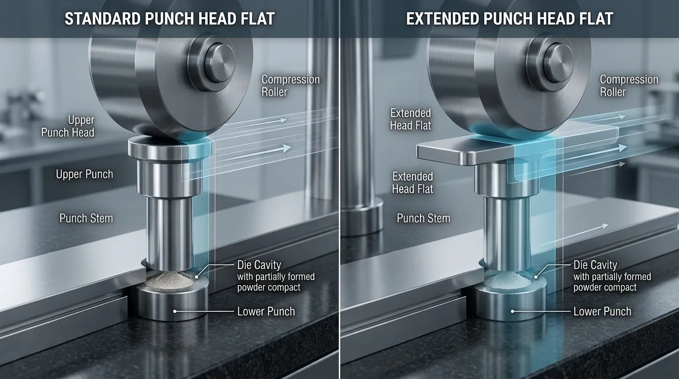
The punch head contacts the compression roller as the tooling moves through the compression zone. The flat region of the head affects the period during which the punch remains at or near its maximum penetration.
That period is commonly described as dwell time. It gives the powder bed additional time for particle rearrangement, deformation, fragmentation, and bond formation under compression.
Dwell is not determined by turret revolutions per minute alone. It is influenced by:
- punch-head profile;
- head-flat dimensions;
- turret speed;
- pitch-circle diameter;
- compression-roller geometry;
- punch velocity through the compression zone.
Two presses running at the same turret speed may therefore expose the formulation to different loading rates and dwell conditions.
A formulation with strong strain-rate sensitivity may form acceptable tablets when compressed slowly but lose tensile strength as punch velocity increases. In that case, a longer head flat may extend the high-compression portion of the cycle and provide more consolidation time.
A peer-reviewed study on punch-head design and metformin tablet quality found that changing the head design affected dwell and the resulting physical properties of the tablets under the studied conditions. The result supports the mechanism, but it does not establish one ideal head-flat size for every formulation or press.
When an Extended Head Flat May Help
An extended head flat deserves evaluation when:
- capping appears or becomes worse as turret speed increases;
- the formulation performs better at slower compression rates;
- tablet strength declines when moving from a development press to a faster rotary press;
- a controlled lower-speed trial improves the defect;
- die inspection does not reveal a more direct mechanical cause;
- the formulation has demonstrated strain-rate sensitivity.
The modified head must still be compatible with the press, rollers, turret, guides, and tooling standard. Increasing the flat is not simply a matter of adding more material. The profile must pass through the complete machine cycle without interference or excessive mechanical loading.
Production consequences must also be considered. Reducing turret speed may prove that additional dwell helps, but it may not be an acceptable permanent solution because output falls. A compatible extended-head-flat design may preserve more output, but only after the mechanism and machine limitations are confirmed.
When Longer Dwell Is Unlikely to Solve Capping
Longer dwell is a weak solution when:
- the formulation has poor inherent bonding;
- binder, moisture, granulation, or lubricant conditions are outside the suitable range;
- the defect does not change during controlled speed trials;
- dies have severe wear or scoring;
- tablets are damaged mainly during ejection;
- excessive elastic recovery remains after dwell changes;
- increasing consolidation time improves hardness but creates friability, dissolution, or other quality problems.
There is no universal ideal dwell time. The relevant measure is whether a controlled dwell change produces a repeatable improvement while other variables remain stable.
Inspect the Dies, Clearance, and Bore Condition
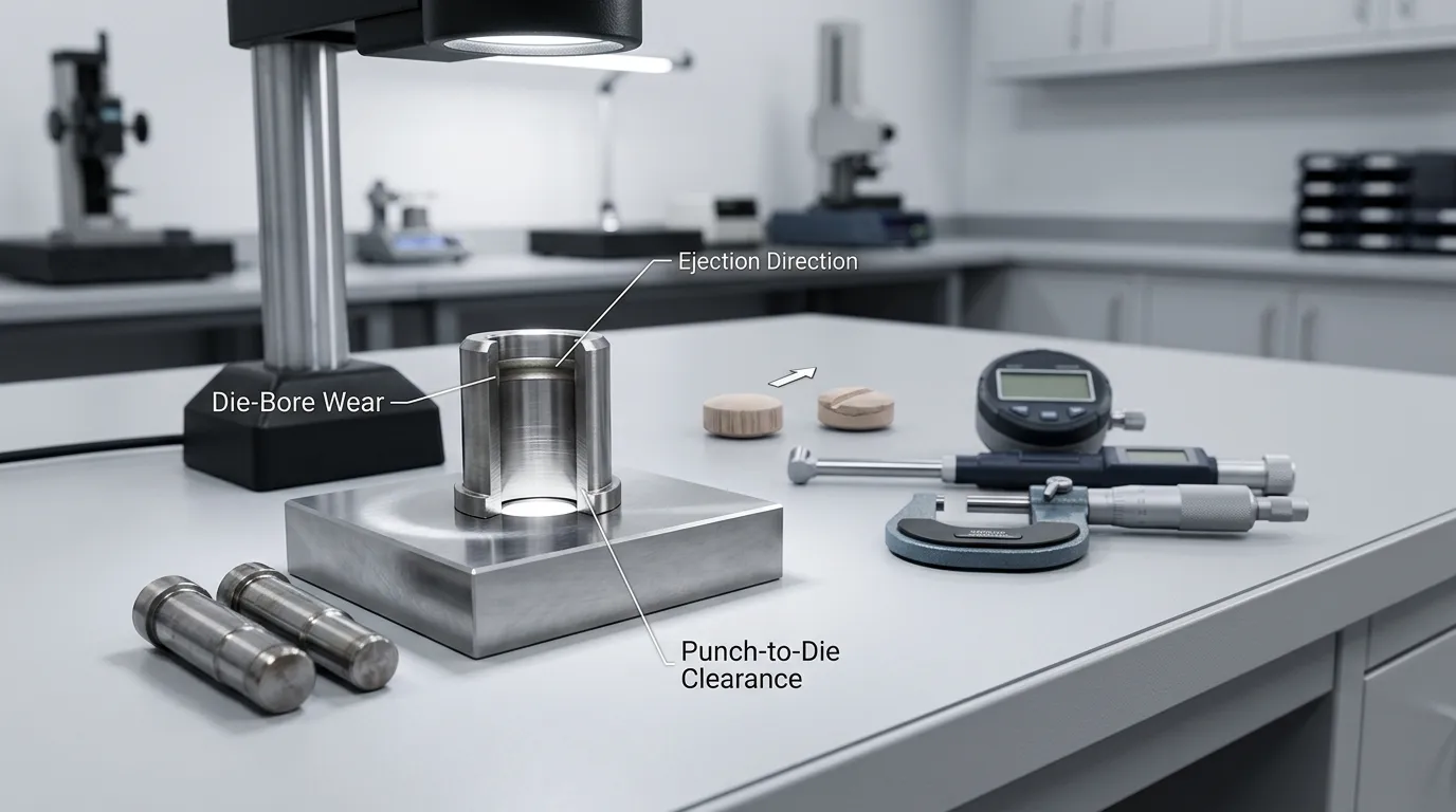
The die controls the powder bed during filling, compression, decompression, and ejection. Its bore condition can influence friction, residual stress, tablet movement, and surface damage.
Clean the die before inspection. Deposits can hide wear or create a false impression of bore damage. Then examine and measure the following:
- Bore surface: Look for scoring, roughness, corrosion, adhered material, and polishing differences.
- Wear-ring area: Check for localized enlargement where maximum compression repeatedly occurs.
- Bore profile: Compare measurements at several heights rather than relying on one diameter reading.
- Punch-tip-to-die clearance: Compare good and problematic stations against the approved tooling drawing.
- Punch-tip condition: Inspect edges, cups, lands, and relief areas for wear or damage.
- Station pattern: Determine whether defects follow a specific die, punch, or turret position.
- Ejection marks: Inspect the tablet belly band for scratches, drag marks, or localized damage.
A wear ring may increase resistance as the tablet moves from an enlarged compression zone into a narrower part of the bore. Roughness and scoring can also raise die-wall friction. Both conditions can increase ejection stress and expose a tablet that already has weak internal bonding.
There is no universal wear or clearance limit that applies to every tablet size, tooling standard, formulation, and press. Acceptance should be based on approved drawings, inspection methods, historical performance, and application-specific engineering review.
SunshinePro’s tablet press tooling page states that tablet punches and dies can be processed from drawings or samples. Its stated tolerance accuracy should be treated as a general product-page claim, not as an automatic guarantee for every feature of every tooling order.
Straight Dies Versus Tapered Dies
A straight die maintains its specified bore profile through the working section. A tapered die includes a deliberately changing diameter in a defined area.
| Die option | Potential reason to evaluate it | Evidence needed | Main limitation |
| Straight die | Standard compression and ejection conditions | Stable compression, acceptable friction, and no air-release problem linked to geometry | Does not address every air-entrapment or ejection mechanism |
| Tapered die | Application-specific support for air release, decompression, or ejection | Reproducible evidence linking capping to one of those mechanisms | Taper direction, amount, length, and location are not universal |
| Replacement die with corrected bore | Existing die is worn, scored, or dimensionally unsuitable | Bore measurements, station pattern, and ejection evidence | Replacement will not correct a formulation failure |
A tapered die should not be selected merely because capping exists. The intended mechanism must be identified first. Taper designed to influence air release is a different engineering decision from taper intended to change tablet release or ejection behaviour.
SunshinePro’s website does not specifically confirm tapered tablet-die capability. Any such requirement would need written feasibility confirmation based on the exact drawing and application.
Account for Trapped Air, Precompression, and Decompression
Powder contains air within the spaces between particles. As the punches enter the die and reduce the powder-bed volume, that air must escape or be redistributed.
If compression occurs too rapidly, internal air pressure can rise before sufficient venting and consolidation take place. Research on air-pressure development within a compressed powder bed connects this internal pressure with defects including cracking, bubbling, and capping.
Precompression can help by applying an earlier, lower compression event before main compression. Its purpose may include:
- removing part of the entrapped air;
- beginning particle rearrangement;
- forming a weak initial compact;
- reducing the abruptness of the main-compression event.
More precompression is not automatically better. Its effectiveness depends on penetration, loading rate, formulation behaviour, and the relationship between the precompression and main-compression stages. A study of precompression and main compression in ibuprofen tablets showed that these settings can materially affect resulting tablet properties under the tested conditions.
During decompression, the applied load is removed and the compact recovers elastically. If interparticle bonds are too weak, or internal air and residual stresses are too high, the crown may begin separating at this stage.
Tooling geometry, press settings, and formulation behaviour must therefore be evaluated together. A modified die cannot compensate for every air-management problem, and additional dwell cannot always overcome poor bonding.
Check Die-Wall Friction and Ejection Stress
After compression, the lower punch pushes the tablet upward through the die. The tablet remains in contact with the bore, and its resistance to movement depends on surface condition, lubrication, radial pressure, material properties, and tooling dimensions.
High die-wall friction may be associated with:
- rough or scored die surfaces;
- a wear ring;
- adhered product;
- inadequate lubrication;
- inconsistent lubricant distribution;
- unsuitable punch-tip-to-die clearance;
- high residual radial pressure;
- an abrasive formulation.
Warning signs include heavy belly-band marks, delayed crown separation, rising ejection resistance, station-specific defects, or tablets breaking as they leave the die.
Ejection-force trends are generally more informative than one isolated reading. A gradual rise during production may indicate increasing deposits, temperature-related changes, or lubrication problems. A sharp difference at one station may point toward local die or punch condition.
No universal ejection-force threshold can be applied to every product. The measurement must be interpreted against tablet size, formulation, press setup, tooling dimensions, historical performance, and the validated process.
Use a Controlled Troubleshooting Sequence
Changing speed, force, precompression, lubrication, and tooling at the same time may reduce the defect, but it will not reveal which change worked. Use a controlled sequence instead.
- Confirm the defect. Record whether the failure is capping, lamination, chipping, or another defect.
- Record when it appears. Note compression, decompression, ejection, dedusting, handling, or delayed testing.
- Map affected stations. Determine whether capping follows individual punches, dies, or turret positions.
- Hold the formulation stable. Avoid comparing unrelated batches when testing tooling hypotheses.
- Inspect punches and dies. Clean, measure, and compare good and defective stations.
- Run a controlled speed trial. Change turret speed while holding other practical variables constant.
- Evaluate precompression separately. Adjust one relevant condition at a time and document the response.
- Review ejection behaviour. Check tablet surfaces, die condition, and available force trends.
- Trial one tooling change. Do not test a new die, extended flat, different cup, and new material simultaneously.
- Define success before the trial. Specify acceptable visual defects, tensile strength or breaking force, thickness, friability, output, and relevant process limits.
The FDA dosage-form inspection guide discusses the need to maintain tablet punches and dies and to use appropriate in-process controls. A troubleshooting trial should therefore consider more than the visual disappearance of capping. The resulting tablet must still meet its broader quality requirements.
Match the Evidence to the Tooling Response
| Observation | Likely mechanism to investigate | Confirmation test | Possible response | Limitation |
| Capping increases with speed and improves when speed falls | Insufficient dwell or strain-rate sensitivity | Controlled speed comparison | Evaluate compatible extended-head-flat tooling | Will not fix poor inherent bonding |
| Defect follows one die position | Local wear, roughness, contamination, or dimensional change | Clean, inspect, measure, and swap positions where permitted | Repair or replace after engineering assessment | Replacement does not correct batch-wide formulation failure |
| Capping changes with precompression | Air release or early consolidation problem | Controlled precompression trial | Optimize process; evaluate tooling geometry only if evidence supports it | Excessive precompression can create other problems |
| High ejection resistance and belly-band damage | Die-wall friction or bore condition | Review force trend and inspect die surface | Correct lubrication, surface, clearance, or damaged tooling | No universal force limit applies |
| Capping persists across speeds and tooling stations | Formulation or broader process limitation | Compaction and formulation review | Return to formulation or process development | New tooling may add cost without correcting the mechanism |
| Crown geometry appears highly stressed | Cup or land design may contribute | Compare approved designs and mechanical results | Review punch-face geometry | Belongs to a separate design evaluation |
Consider Cup Depth Without Turning It Into the Default Fix
Cup depth and punch-face edge geometry affect tablet shape, volume, crown thickness, and stress distribution. Deep cups or unsuitable edge geometry may create mechanical conditions that contribute to cracking or cap separation in some products.
Changing the cup can also alter tablet appearance, weight-volume relationships, edge strength, packaging behaviour, and compression response. It should not be treated as a simple secondary adjustment after dwell or die changes fail.
Detailed selection belongs in the guide to tablet punch cup depth design. For a capping investigation, cup depth should remain one possible contributing factor rather than the default explanation.
Prepare the Data a Tooling Supplier Needs
A supplier cannot responsibly evaluate “anti-capping tooling” from the defect name alone. Prepare a technical data package that includes:
- tablet press manufacturer and model;
- tooling standard and approved drawings;
- turret speed and number of stations;
- available press geometry or dwell information;
- current punch-head profile and dimensions;
- upper- and lower-punch drawings;
- die-bore dimensions and inspection results;
- tablet diameter, shape, weight, thickness, cup depth, and land;
- formulation and granulation route;
- evidence of speed sensitivity;
- precompression and main-compression conditions;
- defect photographs;
- affected station numbers;
- bore, punch-tip, and clearance measurements;
- ejection observations or force trends;
- results from controlled trials;
- required material and inspection documentation;
- measurable trial-acceptance criteria.
This information lets the supplier evaluate compatibility and determine whether a replacement die, modified head profile, or another intervention is technically reasonable.
It also prevents an expensive mistake: ordering a complete tooling set before proving that the current tooling caused the defect.
What SunshinePro Can and Cannot Be Claimed to Provide
SunshinePro’s published tablet-tooling information supports a limited set of company-specific statements.
| Confirmed on the website | Requires direct confirmation |
| Tablet press punches and dies | Extended-head-flat tablet punches |
| Premium high-speed steel listed for the product | Tapered tablet dies designed for capping |
| Custom processing from drawings or samples | Dwell-time calculation or compression-cycle modelling |
| Standard and nonstandard size customization | Compaction simulation or strain-rate testing |
| General punching-head customization | Named TSM or EU tooling-standard compatibility |
| Material-selection advice | Ejection-force testing |
| Material inspection reports stated as available | Guaranteed elimination or reduction of capping |
| Product-page tolerance claim of ±0.002 mm | Application of that tolerance to every feature and order |
The appropriate commercial step is therefore a technical feasibility review, not an assumption that every capping-related modification is already available.
Submit approved drawings, samples where appropriate, inspection data, press details, and trial results through the tablet press tooling product page or the company’s enquiry channel.
Choose the Next Action Based on the Evidence
Use the dominant evidence to decide where the investigation should go next:
- Formulation evidence dominates: return the problem to formulation or process development.
- Speed-sensitive capping improves with controlled dwell changes: evaluate press-compatible head-flat options.
- Air-management evidence dominates: optimize the compression sequence before redesigning the die.
- Die wear or scoring is confirmed: assess repair or replacement against approved dimensions.
- Ejection stress dominates: investigate bore condition, lubrication, clearance, and lower-punch behaviour.
- Cup geometry remains a credible factor: conduct a separate punch-face design review.
- Evidence remains mixed: continue controlled testing rather than ordering a full tooling set.
When the results point to a tooling-related mechanism, send the press information, drawings, defect records, inspection findings, and trial data through SunshinePro’s contact page. The objective should be an application-specific feasibility review of the punches or dies—not a generic request for a guaranteed capping cure.
Share:


Written By Tonmoy
NEWS
GET SERVICE
With quality parts to meet every budget and friendly staff trained to make your visit informative and hassle free.
