



Mold Positioning Pin vs Guide Pin: Alignment Roles Compared
A guide pin and a mold positioning pin both help align mold components, but they normally control different stages of that alignment.
A guide pin travels through a matching guide bushing to control how the mold halves approach, close, and separate. A positioning pin, locator, or interlock usually acts nearer the closed position, where it establishes more exact final registry or helps resist lateral displacement.
The two components are therefore not automatically interchangeable. A conventional mold may rely mainly on guide pins and bushings, while a mold with demanding shut-offs, offset loading, or strict parting-line alignment may use a guide system together with secondary positioning components.
Terminology varies between manufacturers. Some catalogs use “locating pin” as another name for a guide pin, while others use it for a separate final-positioning device. The component’s geometry, mating interface, engagement sequence, and mechanical role matter more than its name. Broader information about guide fits, bushing wear, and maintenance is covered in mold pins and bushings (inferred).
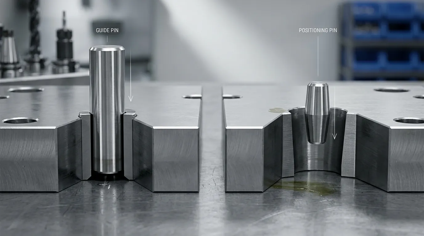
Guide Pin vs Positioning Pin: The Functional Difference
The clearest way to compare the two components is by the function they perform inside the mold.
| Comparison point | Guide pin | Positioning pin or locator |
|---|---|---|
| Primary role | Guides relative movement between mold halves | Establishes or refines the final closed position |
| Typical operating movement | Slides through a guide bushing during opening and closing | Engages a receiver, locating bushing, socket, taper, or contact surface |
| Main operating stage | Begins working during mold-half approach | Often becomes most important near final closure |
| Mating component | Guide bushing or guide sleeve | Locating bushing, receiver, socket, alignment lock, or mating locating surface |
| Fit principle | Requires enough operating clearance for repeated sliding | May use closer, tapered, or positive contact depending on the design |
| Contribution to alignment | Controls approach and general mold-half guidance | Controls final registry or lateral position |
| Side-load role | May experience side loading, but should not automatically be treated as the sole lateral-positioning system | May be selected specifically to help control lateral movement near closure |
| Common wear pattern | Scoring, galling, bushing wear, or increased clearance | Contact-face wear, fretting, peening, taper damage, or loss of final registry |
| Typical system use | Fundamental part of many mold-guidance systems | Added when final-positioning demands exceed what the guide system alone should provide |
A guide pin is commonly called a leader pin, guide post, or guide pillar. It enters a guide bushing and keeps the core and cavity halves moving along the intended path. For deeper coverage of guide geometry, wear, and selection, see mold guide pins.
A positioning component works differently. Its purpose is not necessarily to guide the full mold stroke. It may engage only near closure, where the core half, cavity half, inserts, shut-offs, and parting surfaces must reach a repeatable relationship.
Why Catalog Names Can Be Misleading
Component names are not fully standardized across mold-component catalogs.
“Guide pin” and “leader pin” are often used for the same sliding guide component. “Guide post” and “guide pillar” are also common regional or catalog terms.
“Locating pin” is less consistent. Depending on the supplier or drawing, it may refer to:
- A guide pin that enters a bushing
- A static dowel pin used to locate assembled plates
- A tapered or straight component used for final positioning
- A pin that engages a separate receiver or locating bushing
- Part of a larger alignment-lock or interlock system
A static dowel pin should not be confused with a component that operates throughout mold opening and closing. A dowel may establish the assembled position of two plates, while a guide pin moves repeatedly through a bushing during each cycle.
To identify the component correctly, examine:
- Whether it slides through a bushing
- When it engages during mold closing
- Whether it operates through the full stroke
- Whether its main purpose is movement guidance or final location
- Whether it has straight clearance, tapered contact, or positive locating surfaces
- Which loads the drawing expects it to resist
How Guide and Positioning Components Engage During Mold Closing
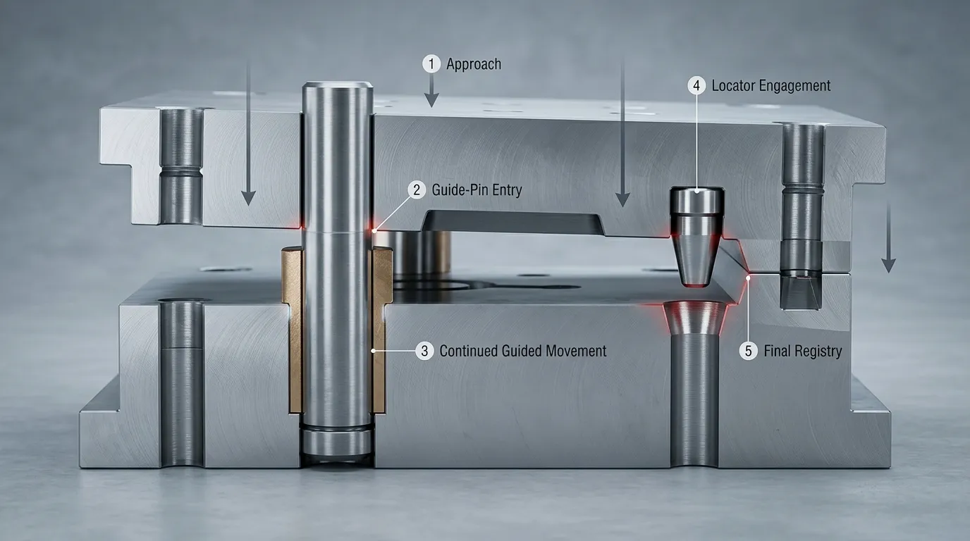
A combined guide and positioning system can be understood as a sequence rather than two components performing the same task.
- The mold halves begin to approach.
The lead-in portion of the guide pin moves toward the guide bushing. - The guide pin enters the bushing.
The pin-and-bushing relationship controls the relative movement of the core and cavity halves. The sliding interface helps prevent uncontrolled lateral movement during approach. - The mold approaches the closed position.
The guide system continues to control movement, but its operating clearance still allows repeated sliding. - The secondary positioning element engages.
Where the design includes a positioning pin, tapered locator, alignment lock, or mold interlock, that component begins controlling the final positional relationship. - Final registry is established.
The parting surfaces, shut-offs, cavities, cores, and related mold features reach their intended closed relationship before or during clamping.
During opening, this sequence reverses. The final-positioning surfaces disengage, and the guide pins continue controlling separation through the guide bushings.
This sequence is a functional example, not a universal timing rule. Actual engagement depends on the component geometry and mold drawing. In some designs, components described as “locating pins” may begin engaging earlier than expected because they also perform a guiding function.
Can a Positioning Pin Replace a Guide Pin?
Usually, a final-positioning component should not be assumed to replace the full-stroke guidance provided by guide pins and bushings. It may not have the length, sliding interface, or engagement range needed to control the mold throughout opening and closing.
The reverse is also true. A guide pin should not automatically be expected to provide every final-positioning function. Its sliding clearance, wear condition, span, and exposure to lateral forces may limit how accurately it controls the final relationship between critical mold features.
The correct arrangement depends on the application.
| Mold condition | Likely alignment approach |
| Conventional mold with moderate alignment demands and limited lateral loading | Guide pins and bushings may be sufficient |
| Mold with irregular parting geometry or demanding shut-offs | Guide system plus secondary positioning may be appropriate |
| Large or heavy mold halves | Additional locating or interlocking support may be required |
| Offset cores, asymmetric forces, or side loading | Final-positioning components may help control lateral registry |
| Critical final alignment between mold features | Guide system and dedicated positioning components may work together |
| Existing binding or movement problems | Inspect guide pins, bushings, mounting alignment, contamination, and wear |
| Existing parting-line mismatch despite acceptable guide movement | Inspect final-positioning and locating surfaces as well as the guide system |
When Guide Pins May Be Sufficient
Guide pins and bushings may provide enough alignment when:
- The mold has conventional parting geometry
- Lateral and asymmetric forces are limited
- Alignment requirements are moderate
- The guide span and component arrangement are suitable
- Pins and bushings remain correctly mounted and within acceptable wear
- There is no recurring evidence of final-registry loss
- The guide system has been selected for the actual mold size and operating conditions
This does not mean that guide pins are imprecise. It means that their main job is controlled movement through a sliding interface. The required running clearance and accumulated wear must be considered when deciding whether they can also satisfy the mold’s final-positioning requirements.
When Secondary Positioning Is More Appropriate
A separate positioning system becomes more relevant when the mold has:
- Deep cavities or demanding shut-off relationships
- Large or heavy moving mold halves
- Irregular, stepped, or non-flat parting surfaces
- Offset loads or asymmetric cavity arrangements
- Side actions that create significant lateral forces
- Critical insert, core, or cavity registry requirements
- Repeated parting-line mismatch that is not caused only by worn guide bushings
- Operating temperatures that materially affect clearance or contact relationships
Secondary positioning does not have to mean one specific pin design. The function may be performed by a straight locator, tapered locator, alignment lock, side lock, or mold interlock.
Straight and tapered positioning geometries create different engagement and contact conditions. That choice should be evaluated separately rather than treated as part of the basic guide-pin comparison.
When Both Systems Should Work Together
Many demanding molds separate the two alignment functions:
- Guide pins and bushings control approach, closing movement, and opening movement.
- Positioning pins, locators, or interlocks refine the final closed position.
This division allows each interface to perform the task it was designed for. The guide components do not have to act as rigid final locks, while the positioning components do not have to guide the mold through its full travel.
The systems still have to be coordinated. If the guide arrangement permits the mold halves to reach a position that conflicts with the locator geometry, the positioning components may strike, bind, or wear unevenly. Mounting accuracy, engagement order, thermal conditions, and the relationship between male and female components must therefore be considered together.
How Fit, Side Load, and Temperature Change the Selection
Fit is one of the main reasons a guide pin and positioning component cannot be evaluated in the same way.
A guide pin must move repeatedly through its bushing. The interface needs operating clearance that accounts for component tolerances, lubrication, contamination, temperature, mounting alignment, and wear. Too little functional clearance can cause binding or galling. Too much clearance can reduce alignment repeatability.
A positioning component may use a different contact principle. A tapered locator or interlock can approach a more positive final relationship as the mold closes. A straight positioning pin may use a controlled fit with a matching receiver. The correct choice depends on how much movement must be allowed before engagement and what load the interface must carry.
Side load also changes the decision. If lateral force acts on the mold halves, guide pins may be pushed against one side of their bushings. Repeated loading can produce uneven wear, increased clearance, or binding. A dedicated positioning system can be used to control the final lateral relationship rather than leaving that entire function to the guide components.
Temperature must be included in the evaluation. Mold plates, pins, bushings, and locating components expand as temperature changes. That expansion can alter sliding clearance or increase contact at locating surfaces. A fit that works during room-temperature assembly may behave differently under operating conditions.
Standardized limits-and-fits terminology, such as the system defined in ISO 286-1, can reduce drawing ambiguity. It does not establish one universal guide-pin or positioning-pin fit. The designer still has to select the tolerance relationship for the actual material, temperature, lubrication, load, geometry, and component function.
Wear and Failure Clues: Which Alignment Function Is Being Lost?
The wear pattern often indicates whether the problem is mainly related to movement guidance or final positioning.
| Observed condition | More likely area to inspect | Why |
| Binding during opening or closing | Guide pins, guide bushings, mounting alignment, contamination | The sliding guide path may be restricted or misaligned |
| Long scoring marks on a pin | Guide interface | Sliding contact, contamination, insufficient lubrication, or side loading may be present |
| Galling or material transfer | Guide pin and bushing pair | Adhesive wear can develop when sliding surfaces contact under unsuitable conditions |
| Uneven bushing wear | Guide system and mold alignment | Side load or mounting error may be forcing contact to one side |
| Increased free movement before closure | Guide clearance | Wear may have enlarged the pin-and-bushing relationship |
| Fretting or polished contact patches on locator surfaces | Positioning system | Repeated contact or micro-movement is affecting final-location surfaces |
| Peening or damaged edges on a locator | Engagement sequence or misalignment | The components may be striking before they are properly aligned |
| Damaged taper or uneven taper contact | Positioning component | Final locating contact may no longer be distributed correctly |
| Parting-line mismatch or shut-off inconsistency | Complete alignment system | Loss of final registry may involve locators, guide wear, plate movement, or other mold conditions |
No single symptom proves that one component has failed. Flash, mismatch, or binding can have several causes. Inspection should include both male and female components, their mounting features, the mold plates, lubrication condition, contamination, and evidence of lateral loading.
Replacing only a worn pin may not restore the original relationship if the mating bushing or receiver is also damaged. The complete interface should be evaluated.
Selection Checklist for Drawings and Supplier RFQs
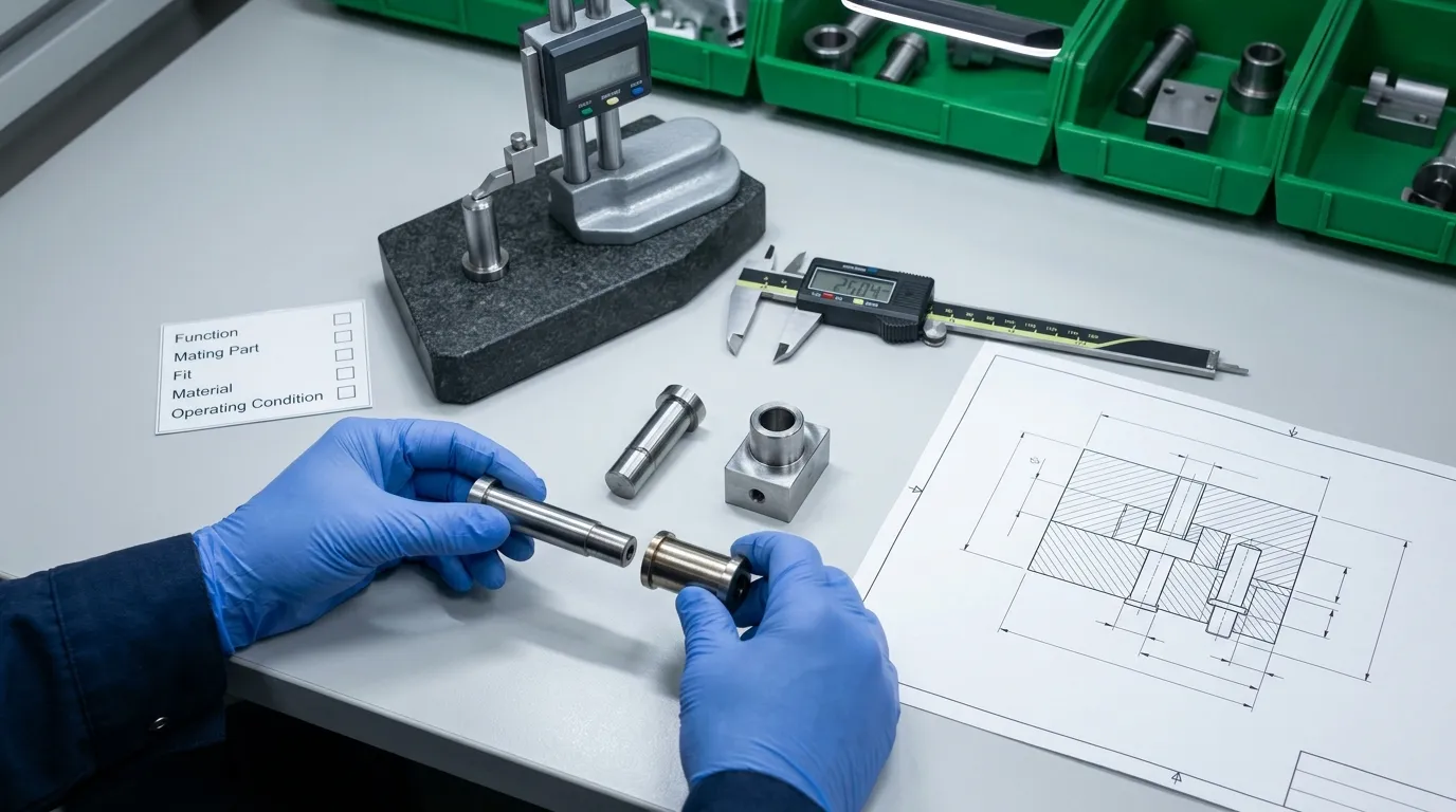
A supplier cannot reliably determine the correct component from the words “guide pin” or “positioning pin” alone. The RFQ should define the required function and the mating relationship.
Include the following information:
- Required function: State whether the component provides full-stroke guidance, final registry, lateral positioning, static plate location, or a combined role.
- Assembly drawing: Provide a mold section showing where the pin, bushing, receiver, or locating surface is installed.
- Mating components: Identify both sides of the interface rather than specifying only the pin.
- Nominal dimensions: Include diameters, lengths, shoulders, tapers, engagement depths, and mounting dimensions.
- Dimensional tolerances: Identify the tolerance for each critical feature and make clear which diameter or surface it applies to.
- Geometric tolerances: Add straightness, concentricity, perpendicularity, or position controls where the design requires them.
- Material and heat treatment: Specify these only according to the approved design or service conditions.
- Hardness and surface finish: State the required features instead of assuming one universal value for all guide or positioning parts.
- Coating or surface treatment: Include it only when required and define the treated surfaces.
- Operating temperature: Describe the expected thermal condition where it may affect clearance or locating contact.
- Lubrication and contamination conditions: Indicate whether the component operates with lubrication and whether dust, resin residue, or other contamination is expected.
- Load direction: Identify unusual lateral, offset, or asymmetric loading.
- Installation method: Define press-fit, retained, shouldered, flanged, or other mounting requirements.
- Replacement access: Show how the component will be removed and whether the mating part is replaceable.
- Inspection requirements: Request dimensional reports or other records where critical features require verification.
The sourcing route also matters. A catalog component may be appropriate when the required geometry, fit, material, and mounting method match an established standard. A drawing-based component may be needed when the mold has unusual engagement geometry, nonstandard dimensions, special mating surfaces, or application-specific material requirements.
SunshinePro publishes guide posts, bushings, locating-related accessories, and other mold standard parts. The company also states that custom mold and die accessories can be produced from drawings or samples. Those broad capabilities do not replace the need for a complete technical specification.
Choosing the Correct Alignment System for the Mold
There is no universal winner in the mold positioning pin vs guide pin comparison.
Use guide pins and bushings when the mold needs controlled relative movement during opening and closing. Use a positioning component when the design requires more definite final registry, better control of lateral displacement, or repeatable contact near the closed position. Use both when movement guidance and final positioning are separate requirements.
The final decision should come from the mold drawing, parting geometry, expected loads, operating temperature, allowable clearance, mating-component design, and maintenance access—not the catalog name alone.
For a standard-part or drawing-based component review, prepare the mold section, required function, mating geometry, dimensions, tolerances, material requirements, and operating conditions before contacting SunshinePro.
Share:


Written By Tonmoy
NEWS
GET SERVICE
With quality parts to meet every budget and friendly staff trained to make your visit informative and hassle free.
