



Custom Punch Pin Drawing Checklist for Faster, More Accurate RFQs
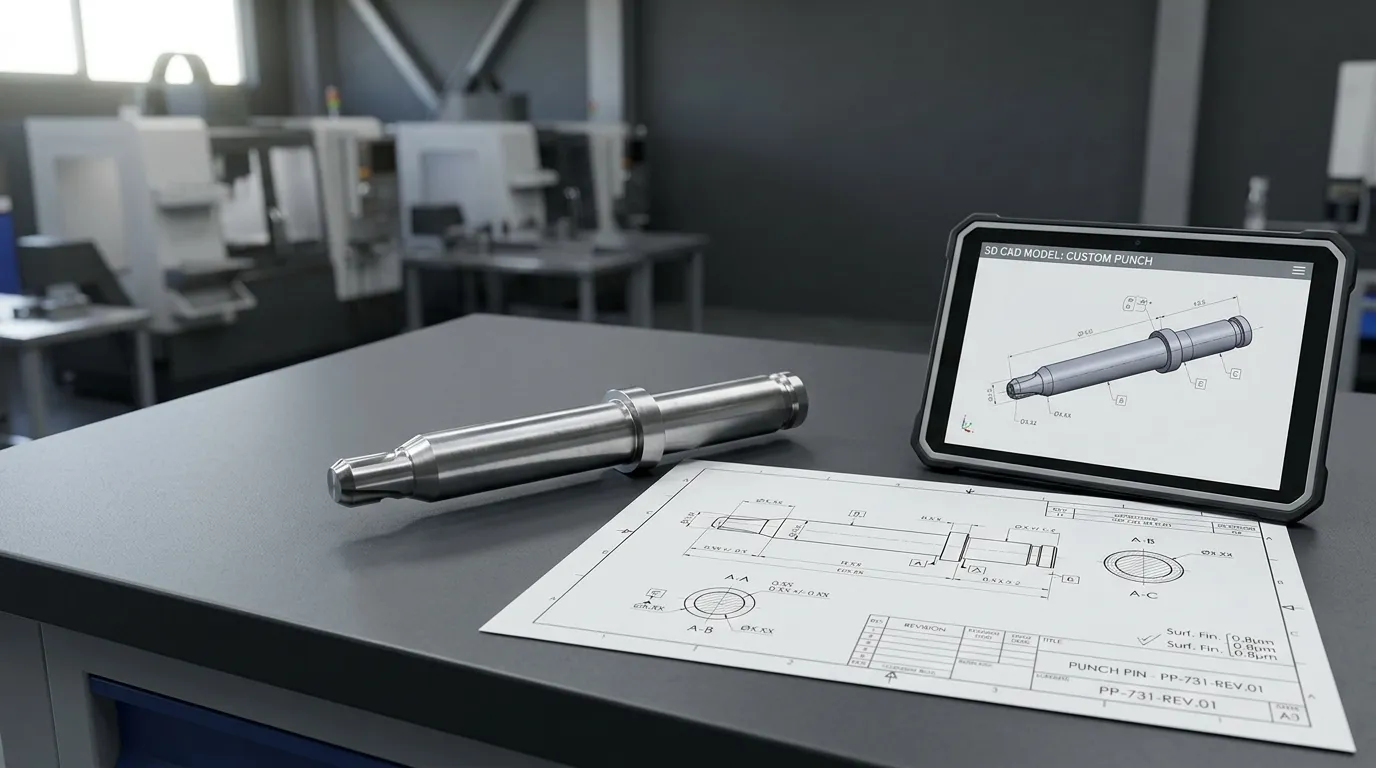
A custom punch pin drawing should define more than the working diameter or tip profile. A supplier also needs the mounting interface, material condition, functional tolerances, application context, inspection requirements, and controlled revision before preparing a reliable quotation.
This checklist is for made-to-print punch pins used in stamping, piercing, forming, recess punching, cold heading, and related tooling applications. For broader information about how punches interact with other die parts, see the die components guide (inferred).
A complete package cannot guarantee a particular quotation time, price, or manufacturing outcome. It can, however, reduce avoidable questions caused by missing dimensions, inconsistent files, vague material notes, or undefined acceptance requirements.
Separate Drawing Requirements from RFQ Information
Not every quotation detail belongs on the engineering drawing. The controlled drawing should define the part, while the RFQ should explain the purchasing scope and operating context.
| Information | Where It Belongs | Why It Matters |
|---|---|---|
| Part geometry and dimensions | Controlled drawing | Defines the part to be manufactured |
| Datums and tolerances | Controlled drawing | Establishes functional and inspection requirements |
| Material and final condition | Controlled drawing | Defines the required material state |
| Surface texture and treatment areas | Controlled drawing | Identifies controlled surfaces |
| Drawing number and revision | Drawing and file names | Prevents quotation against an obsolete definition |
| Order quantity | RFQ | Defines the commercial scope |
| Machine and die application | RFQ or technical attachment | Helps the supplier review how the punch will be used |
| Workpiece material and thickness | RFQ | Provides application context |
| Inspection documents | RFQ and drawing notes where applicable | Defines required deliverables |
| Requested delivery date | RFQ | Supports production and logistics planning |
| Photos or damaged samples | Supporting attachment | Helps explain replacement or failure conditions |
| 3D CAD model | Supporting technical file | Communicates nominal geometry, especially complex profiles |
A drawing can be technically complete while the RFQ remains commercially incomplete. The reverse is also possible: a detailed purchasing email cannot compensate for an undefined holder fit, missing radius, or vague tolerance note.
Define the Source of Truth Before Quotation
The supplier should not have to decide which file is correct when the drawing, model, sample, and email notes disagree.
Establish a clear document hierarchy:
- Identify the controlled drawing and current revision.
- Confirm that the 3D model matches that revision.
- Mark any reference-only dimensions or files.
- Explain whether a supplied sample is authoritative or only supplementary.
- Record proposed supplier deviations and require approval before they are adopted.
A worn or modified sample should not automatically override the drawing. Likewise, an email note should not silently change a controlled dimension without an updated document or written deviation approval.
Check the Drawing Identity and Basic Technical Data
Start the custom punch pin drawing checklist with document control. These details may appear administrative, but they determine how the supplier interprets, quotes, manufactures, and inspects the part.
Check that the drawing includes:
- Part name
- Unique drawing or part number
- Current revision
- Revision or issue date
- Units
- Scale
- Sheet number and total sheet count
- Material field
- General tolerance
- Governing drawing and tolerancing standard
- Referenced drawings or specifications
- Approval or release status, where required
The drawing number and revision should also appear consistently in the PDF filename, CAD filename, RFQ, and supporting documents.
Title-block information can be organized using principles from ISO 7200, which covers data fields used in technical document headers and title blocks.
The drawing should also identify the governing tolerancing framework. For example, ASME Y14.5 and the ISO geometrical product specification system use established rules for interpreting dimensions and geometric controls. Do not mix conventions without making the governing standard and edition clear.
Define Every Functional Punch Feature
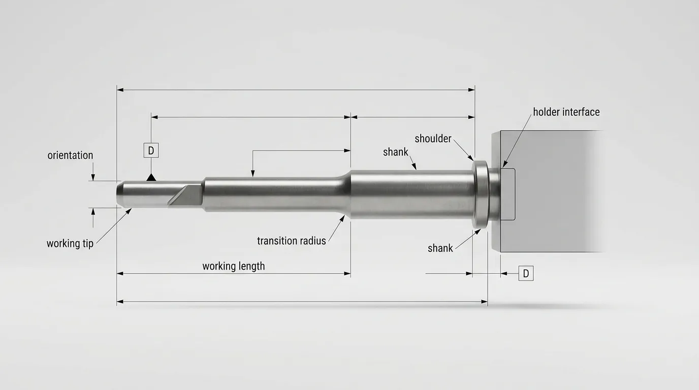
A punch pin cannot be quoted accurately when only its tip diameter and total length are shown. The drawing must define every feature that affects its operation, support, location, retention, and fit.
Review the part in functional groups:
- Working tip or profile
- Cutting, forming, or recess edge
- Working length
- Body and shank
- Unsupported section
- Transition features
- Holder interface
- Head, shoulder, flange, thread, flat, or other retention feature
- Orientation features
- Reliefs, lands, tapers, and chamfers
- Internal holes or special forms, where applicable
Distinguish overall length from working length. Overall length describes the complete part, while working length identifies the section involved in the operation. Unsupported length may also be relevant where a long punch extends beyond its guide or holder.
Avoid duplicated dimensions that control the same feature from different origins. Redundant dimensions can produce conflicting tolerance stacks or unclear inspection results.
Specify the Working End and Edge Condition
The working end should describe what the punch actually does. State whether it pierces, blanks, forms, creates a recess, or performs another defined operation.
Depending on the application, the drawing may need to show:
- Tip diameter or complete profile
- Corner and transition radii
- Sharp, radiused, chamfered, or relieved edge condition
- Land length
- Taper or relief angle
- Polished or finished areas
- Orientation of a non-round profile
- Working or insertion direction
- Blind depth or internal profile details
A complex profile should not be left to an informal description such as “special shape.” Use adequate views, sections, dimensions, or profile controls. ISO 1660 provides rules for profile tolerancing when line or surface profile specifications are appropriate.
Define the Holder, Shank, and Retention Interface
A correctly shaped tip is not enough if the punch cannot fit, locate, or remain secure in its holder.
Check the drawing for:
- Shank diameter and length
- Required fit with the holder or guide
- Locating shoulder or face
- Head or flange dimensions
- Thread size and depth
- Flat, keyway, pin hole, or orientation feature
- Supported length
- Insertion direction
- Mating surface requirements
Include a holder drawing, assembly section, or mating-part reference when the interface cannot be understood from the punch drawing alone.
The functional mounting surfaces should also influence the datum strategy. A datum selected only because it is easy to dimension may not represent how the punch is located during operation or inspection.
State the Material and Final Part Condition
Material descriptions such as “tool steel,” “HSS,” or “carbide” may be too broad for a controlled custom part. Where the material has already been approved, specify the exact grade, condition, and governing material designation.
Where the material has not been finalized, make the request explicit. For example, state that the supplier may recommend a material based on the defined application, but any substitution or alternative must be documented and approved.
The drawing package may need to address:
- Exact material grade
- Material standard
- Permitted equivalent grades
- Heat-treatment condition
- Required hardness range
- Hardness scale
- Coating or surface treatment
- Treated and untreated areas
- Masking requirements
- Ground or polished surfaces
- Surface-texture requirements
- Corrosion protection or storage preservation
- Material, hardness, or treatment documentation
A hardness value without its scale is incomplete. A coating name without the treated area is also ambiguous.
Surface-texture requirements should identify the affected surface and the applicable parameter rather than applying one roughness value to the entire punch without a functional reason. ISO 21920-1 covers the indication of surface texture in technical product documentation.
Clarify When Dimensions and Finish Requirements Apply
Heat treatment, coating, grinding, and polishing may change dimensions or surface conditions. The drawing should state when the part must comply with its final requirements.
Confirm whether dimensions and tolerances apply:
- Before or after heat treatment
- Before or after coating
- Before or after final grinding
- Before or after polishing
- With or without coating thickness included
- In the condition used for final inspection
Also identify coating boundaries and masked areas where applicable. Without a finished-condition note, the supplier may not know whether a dimension controls the pre-treatment feature or the completed punch.
Add Functional Tolerances, Datums, and Inspection Requirements
Tolerance decisions should follow the function of the punch. A blanket tight tolerance across every dimension can increase manufacturing and inspection complexity without improving operation.
The drawing should distinguish between:
- General tolerances for non-critical dimensions
- Individual size tolerances
- Fit-related dimensions
- Working-profile controls
- Form controls
- Orientation controls
- Location controls
- Axis-related controls
- Surface-profile requirements
Datums should reflect how the punch is located, mounted, used, or inspected. ISO 5459 defines rules for datums and datum systems, while ISO 1101 addresses geometrical tolerancing symbols and interpretation.
Avoid vague notes such as:
- “Perfectly straight”
- “Exactly concentric”
- “No runout”
- “Precision fit”
- “All dimensions critical”
These statements do not define an acceptance boundary. Use the appropriate dimensional or geometric control under the declared standard.
Axis-related requirements need particular care. Runout, coaxial relationships, and concentricity-related terminology are not interchangeable simply because they involve cylindrical features. The correct control depends on the functional relationship, datum system, and inspection method.
Separate General Tolerances from Critical Controls
Use the drawing’s general tolerance for dimensions that do not require individual control. Apply tighter or more specific requirements only where they protect a functional need.
Features that may justify separate controls include:
- Holder-fit diameter
- Working-tip size
- Profile relative to the shank
- Shoulder location
- Locating face
- Long body straightness
- Working face perpendicularity
- Orientation of a keyed or non-round profile
The drawing should make the functional reason clear through its datum structure and dimensioning scheme. It should not create multiple overlapping controls for the same relationship.
For broader die-level tolerance and tooling considerations, the punching dies guide provides additional context.
Match Critical Requirements to an Inspection Plan
A tolerance is useful only when it can be verified in the required condition.
For each critical characteristic, determine:
- What feature will be measured
- Which datum setup applies
- Whether actual measured values are required
- Whether first-article inspection is needed
- Whether production sampling is acceptable
- Which document must accompany the shipment
- Whether material or hardness records are required
Possible deliverables include:
- Dimensional inspection report
- First-article report
- Material certificate
- Hardness report
- Coating or treatment certificate
- Certificate of conformity
These documents should be requested only when they serve a technical, contractual, or traceability purpose. Do not assume that every document is included by default.
Add the Application Context the Drawing Cannot Show
The supplier needs to understand how the punch will be used, especially when reviewing material, geometry, support, or replacement conditions.
Include relevant application information in the RFQ:
- Operation performed
- Machine or press identification
- Die type
- Die station
- Holder or guide arrangement
- Workpiece material
- Workpiece thickness
- Coated, hardened, or abrasive workpiece condition
- Lubrication or process conditions
- Production volume or duty pattern
- Existing wear or failure observations
- Reason for replacement or redesign review
Application information should support technical review, not replace controlled drawing requirements. Stating the workpiece material does not remove the need to define the punch geometry, material condition, and acceptance criteria.
Document Failure History for Replacement Punches
When replacing a worn, chipped, bent, reworked, or broken punch, include evidence of what happened.
Useful supporting information includes:
- Clear photographs
- Failure location
- Wear pattern
- Approximate point in the production cycle when the problem occurs
- Regrinding or polishing history
- Repairs or undocumented modifications
- Original drawing, if available
- Mating-part or holder condition
- Remaining surfaces believed to represent the original geometry
A damaged sample may help with inspection or reverse engineering, but it may no longer represent the original design. State whether the supplier should reproduce the sample, compare it with the drawing, or propose a reviewed change.
For a deeper discussion of failure causes, see punch breakage in stamping dies.
Complete the Commercial and File Package
Once the technical definition is ready, complete the quotation package with the purchasing information needed to price the correct scope.
Include:
- Required quantity
- Optional quantity breaks
- Expected repeat or annual demand, if known
- Prototype, replacement, or production status
- Requested quotation date
- Required delivery destination
- Target delivery date
- Part-marking requirements
- Packaging and preservation requirements
- Required inspection documents
- Technical contact person
- Permission to propose alternatives
- Approval process for deviations
Attach only the current files:
- Controlled 2D drawing
- Matching 3D CAD model
- Assembly or mating drawing
- Relevant specifications
- Sample photographs
- Failure photographs
- Inspection records
- Marked-up clarification document, where needed
Do not assume that one CAD format is accepted by every supplier. Confirm the preferred format when necessary.
Confirm the 2D Drawing and 3D Model Match
Before sending the RFQ, compare the drawing and model directly.
Verify that they have:
- The same part number
- The same revision
- The same units
- The same nominal geometry
- The same feature orientation
- A clear source-of-truth statement
- No obsolete or duplicate files in the attachment set
A 3D model can communicate complex nominal geometry efficiently, but it may not contain all tolerance, finish, material, inspection, and revision requirements. The controlled drawing should define how the part is accepted unless another approved product-definition method is explicitly established.
Run a Final Pre-Submission Drawing Audit

Use this final checklist before releasing the custom punch pin drawing package.
| Audit Item | Status | Pass Condition |
| Application identified | Required | Operation, machine, die, and workpiece context are clear |
| Controlled drawing identified | Required | Part number and current revision are unambiguous |
| Working profile complete | Required | Tip, edge, radii, reliefs, and orientation are defined |
| Holder interface complete | Required | Shank, locating, support, and retention features are defined |
| Lengths complete | Required | Overall, working, and relevant unsupported lengths are shown |
| Material condition defined | Required | Grade is specified or a recommendation process is stated |
| Final condition defined | Conditional | Heat treatment, coating, grinding, and inspection stage are clear |
| Functional tolerances defined | Required | Critical controls are tied to functional references |
| Datum system established | Conditional | Precision relationships have clear inspection references |
| Inspection requirements stated | Conditional | Reports, sampling, and certificates are defined where needed |
| Application evidence attached | Conditional | Photos, samples, or failure information are included when relevant |
| Files synchronized | Required | Drawing, model, RFQ, and filenames use the same revision |
| Quantities defined | Required | Current order quantity and useful quantity breaks are supplied |
| Deviations controlled | Required | Supplier changes require documented review and approval |
Any unresolved item should be identified as a question rather than hidden behind a vague note.
Resolve These Red Flags Before Sending the RFQ
Stop and revise the package if it contains:
- Different revisions across the PDF and CAD files
- Undefined units
- No governing tolerancing standard
- A material note such as “good tool steel”
- A hardness number without a scale
- An undefined final treatment condition
- Missing holder or locating geometry
- Critical features without datum references
- Blanket tight tolerances
- Duplicate or conflicting dimensions
- Unspecified edge conditions
- Missing radii at section transitions
- A worn sample with no modification history
- An inspection report request with no identified critical features
- Permission for substitutions without an approval process
These issues do not always make quotation impossible, but they create assumptions that should be resolved before manufacture.
Submit the Package for Technical Review and Quotation
After the package passes the audit, submit the controlled drawing, current CAD file, application details, quantity requirements, and any relevant sample or failure evidence.
Sunshine’s website lists a Punching Dies & Pins category and states that drawings or samples can be provided for custom non-standard accessories. Use the contact page to submit the package for a tailored review, while clearly identifying any unresolved material, tolerance, inspection, or application questions.
Share:


Written By Tonmoy
NEWS
GET SERVICE
With quality parts to meet every budget and friendly staff trained to make your visit informative and hassle free.
