



Slug Pulling Prevention in Stamping Dies: Causes and Fixes
Slug pulling occurs when a pierced slug remains attached to the punch and travels upward during the return stroke. The slug may stay on the punch face, drop back onto the strip, become trapped near the stripper, or return to the working area where it can be struck again.
Effective slug pulling prevention in stamping dies starts with identifying what is holding the slug to the punch. Common mechanisms include vacuum, lubricant adhesion, residual magnetism, burr clamping, unsuitable punch-to-die clearance, worn cutting edges, and insufficient die-wall retention.
Clearance, alignment, die construction, and cutting-edge maintenance are broader tooling fundamentals covered in the punching dies guide (inferred). This guide focuses specifically on diagnosing slug pulling and matching the correction to its actual cause.
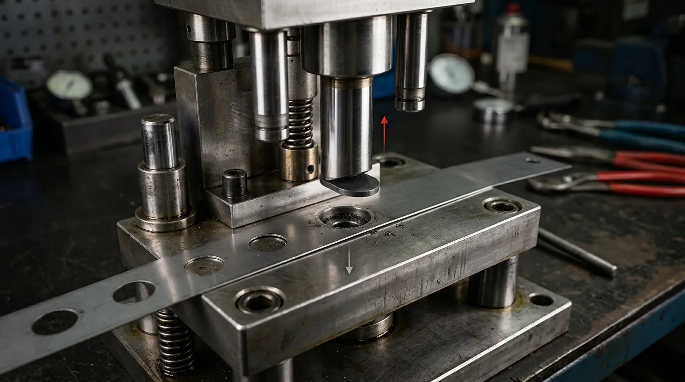
What Slug Pulling Looks Like and Why It Can Damage the Die
During a normal piercing cycle, the punch enters the sheet, separates the slug, and pushes it into the die opening. As the punch retracts, the stripper holds the sheet down while the slug remains in the die channel or continues through the relief area.
With slug pulling, the separated slug follows the punch during retraction. It may remain attached for the full upstroke or release unexpectedly above the die surface.
Typical signs include:
- A slug stuck to the punch face.
- Loose slugs appearing on top of the strip.
- Circular or shaped dents near pierced holes.
- Repeated slugs around the stripper or die surface.
- Feed interruption after a piercing station.
- Unusual impact noise during a subsequent stroke.
- Cutting-edge marks that appear after a double hit.
- Intermittent defects that occur only at normal press speed.
A returned slug can be struck between the punch and strip during the next cycle. This may mark the part, chip a cutting edge, overload a small punch, or interrupt strip movement in a progressive die. If repeated impact is contributing to tool failure, the related punch breakage in stamping dies guide covers the broader fracture and overload mechanisms.
Confirm That the Problem Is True Slug Pulling
Not every slug found near the die surface was carried upward by the punch. Identifying where the scrap becomes uncontrolled prevents the wrong corrective action.
| Condition | What happens | Typical observation | Main area to investigate |
|---|---|---|---|
| True slug pulling | The slug remains attached to the punch during retraction | Slug visible on the punch face or released above the strip | Punch-to-slug sticking forces and die retention |
| Slug stacking | Multiple slugs accumulate inside the die channel | Increasing discharge resistance, blocked relief, compressed slug column | Die land, relief, outlet, and scrap path |
| Slug tumbling or bounce-back | The slug separates but moves unpredictably after release | Loose slug found near the die without evidence of punch attachment | Die exit geometry and scrap control |
| Floating scrap | Detached light scrap returns to the working area through airflow, vibration, or poor evacuation | Loose pieces move independently of the punch | Chutes, outlets, airflow, and scrap handling |
Slow-cycle observation may reveal where the slug releases, but some failures only occur at production speed. High-speed video, where available, can show whether the slug follows the punch, pauses in the die opening, or becomes loose after discharge.
Other useful clues include:
- Oil patterns on the slug or punch face.
- Metallic debris or deposits around the cutting edge.
- A noticeable magnetic attraction between the punch and slug.
- Changes that began immediately after sharpening.
- A failure that appears only after increasing press speed.
- A slug that is already detached before it reaches the die surface.
Scrap suction can help remove detached light scrap, but it does not directly release a slug that is still attached to the punch. Component roles such as the punch, die button, stripper, guide elements, and wear parts are covered more broadly in the die components guide.
Why a Slug Follows the Punch During Retraction
Slug pulling is best understood as a force-balance problem. Forces holding the slug against the punch act against forces that retain the slug in the die or push it away from the punch.
According to peer-reviewed research on slug-pulling mechanisms, the dominant mechanism can change with punch diameter, clearance, penetration depth, cutting speed, lubricant viscosity, edge condition, and material behavior. Several mechanisms may also act at the same time.
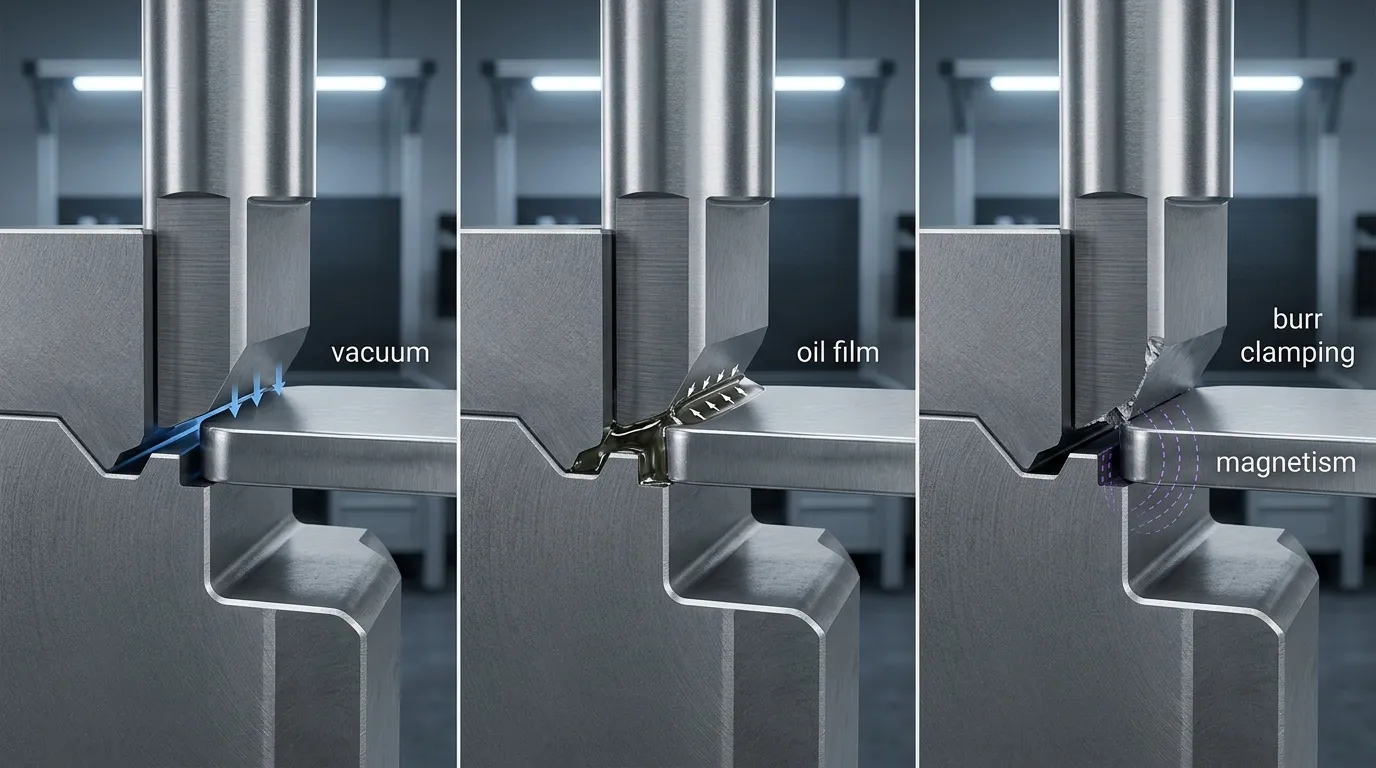
Vacuum and Oil-Film Adhesion
After the slug separates, a small sealed space may form between the punch face and the slug. As the punch retracts, pressure in that space can fall below the surrounding pressure. The resulting vacuum force helps keep the slug against the punch face.
Vacuum-related pulling may become more influential when:
- The slug has broad, flat contact with the punch face.
- The punch retracts quickly.
- Air cannot enter the space easily.
- The punch travels deeply into the die.
- The punch diameter creates a relatively large sealed area.
- Lubricant helps maintain the seal.
Lubricant can also create its own adhesive force. A thick oil film between the punch face and slug may resist separation, especially when the lubricant has high viscosity or is applied excessively.
That does not mean lubrication should simply be removed. Lubricant may be necessary for tool wear control, strip movement, and part quality. The correct response is to review the lubricant type, quantity, temperature, and application consistency through controlled trials.
Residual Magnetism and Burr Clamping
A steel punch can retain magnetism after grinding, sharpening, or contact with magnetic workholding equipment. If the slug material is ferromagnetic, magnetic attraction may be enough to carry a small or light slug upward.
Residual magnetism is especially suspect when slug pulling begins immediately after:
- Punch sharpening.
- Surface grinding.
- Magnetic chuck use.
- Punch replacement.
- Maintenance involving magnetic tools.
Burr clamping is a different mechanism. During fracture, the slug edge may develop a burr that mechanically grips the punch cutting edge. Worn edges, chipping, unsuitable clearance, and changes in fracture geometry can increase this gripping action.
The distinction matters. Demagnetizing will not correct mechanical clamping, while sharpening alone will not remove residual magnetism.
Insufficient Die Retention or Incorrect Slug Release
The die channel must perform two tasks that can conflict with each other. It must resist the slug’s upward return, but it must also allow the slug to travel downward without stacking or excessive compression.
Punch-to-die clearance affects:
- Fracture behavior.
- Slug size and deformation.
- Burr direction and size.
- Contact between the slug and die wall.
- Cutting and stripping forces.
- The slug’s ability to move through the die.
Excessively open clearance may reduce useful die-wall retention or create unstable slug behavior. Excessively tight clearance may increase cutting force, wear, burr-related clamping, or slug compression.
Die land length, relief geometry, internal wear, deposits, and damaged transitions also affect the holding and release forces. Research on die-to-slug contact stresses shows that die geometry and radial contact influence slug-retaining friction. More compression is not automatically better; excessive plastic deformation may reduce the effective retaining stress or contribute to stacking.
There is therefore no universal clearance percentage that prevents slug pulling in every material, thickness, and punch geometry.
Diagnose the Cause Before Modifying the Tool
A structured investigation is usually more effective than immediately adding an ejector, changing clearance, or modifying the die.
- Confirm that the slug follows the punch.
Observe the slug during retraction and determine whether it remains attached, releases near the stripper, or becomes loose only after leaving the die. - Identify what changed before the failure appeared.
Check for recent sharpening, a new material coil, a lubricant change, higher press speed, component replacement, die regrinding, or clearance adjustment. - Record where the slug releases.
A slug that stays attached throughout the upstroke may indicate a strong vacuum, oil adhesion, magnetism, or burr clamping. A slug that releases near the die entrance may indicate marginal retention. - Inspect the punch face and cutting edge.
Look for wear, chipping, built-up material, oil residue, burr marks, or circular witness marks from repeated contact. - Inspect the die channel.
Check the land, relief, wall condition, deposits, damage, and evidence of slug stacking. - Check for residual magnetism.
Compare the punch’s attraction before and after demagnetizing when magnetic sticking is suspected. - Verify the actual clearance.
Do not rely only on the nominal drawing. Confirm punch size, die opening, wear, and clearance per side in the current tool condition. - Review punch penetration.
Too little penetration may fail to advance the slug into a retaining or relief region. More penetration, however, may increase the volume change beneath the punch and strengthen vacuum during withdrawal. - Compare slow and production-speed behavior.
A setup that works during slow cycling may fail when withdrawal speed, lubrication, vibration, and thermal conditions reach normal production levels. - Change one variable at a time.
If clearance, lubrication, speed, and penetration are changed together, the team cannot reliably identify which adjustment corrected or worsened the problem.
All inspection and testing should follow the plant’s approved press-safety and toolroom procedures.
Match the Fix to the Confirmed Cause
Start with reversible maintenance and setup corrections. Move to process changes next. Punch-side or die-side modifications should follow only when the observed mechanism justifies them.
Maintenance and Setup Corrections
| Observed condition | Check | Possible correction |
| Problem began after grinding | Residual magnetic attraction | Demagnetize the punch and verify the result |
| Oil film visible between punch and slug | Lubricant amount and viscosity | Correct excessive or inconsistent application |
| Burr or edge marks grip the punch | Cutting-edge wear, chipping, clearance | Restore the edge and recheck actual clearance |
| Deposits on the punch or die wall | Material pickup or contamination | Clean the affected surfaces and investigate the source |
| Uneven witness marks | Punch and die alignment | Correct the alignment before changing geometry |
| Problem began after replacement | Installed dimensions and penetration | Confirm the new component matches the drawing and setup |
These checks are relatively low cost and can reveal whether the failure was introduced by maintenance or setup rather than the original die design.
Process and Geometry Adjustments
Clearance should be reviewed as part of the whole cutting condition, not changed in one direction by default. The correct value depends on the material, thickness, hole size, part-quality requirement, tool condition, and die geometry.
Punch penetration also requires careful evaluation. Increasing entry may help place the slug deeper into a retaining section, but it may also increase vacuum effects. Reducing entry may decrease vacuum volume while leaving the slug insufficiently controlled by the die.
Other controlled adjustments may include:
- Reviewing lubricant quantity and delivery position.
- Comparing lower and normal production speeds.
- Correcting inconsistent material feeding or strip support.
- Restoring the intended die land and relief condition.
- Confirming that the slug can move downward without obstruction.
After each change, check hole quality, burr condition, stripping behavior, tool marks, and scrap movement. A correction that stops slug pulling but creates excessive burrs or die-channel stacking is not a complete solution.
Punch-Side and Die-Side Tooling Modifications
Punch-side modifications act directly on the slug or the pressure beneath the punch:
- Vented punch: Provides a path for pressure equalization and is most relevant when vacuum is the dominant mechanism.
- Mechanical slug ejector: Uses a spring-loaded or resilient element to push the slug away from the punch face.
- Compressed-air blow-off: Applies a timed downward force through or near the punch.
- Shear geometry: Reduces full-face contact or deforms the slug so it separates more easily from the punch.
Die-side modifications increase resistance to upward movement or improve controlled discharge:
- Slug-retention grooves or catcher features: Create local interference below the cutting edge.
- Controlled die-wall contact: Uses the die channel to generate sufficient retaining friction.
- Corrected land and relief geometry: Holds the slug where needed, then permits downward release.
- Repair or replacement: Restores worn or damaged internal geometry.
Each option has limitations. Small punches may not have enough internal space for a vent or ejector. Air passages can clog, consume compressed air, or weaken a slender punch. Ejector elements can fatigue. Shear geometry may create side loading or unacceptable slug deformation. Retention features must remain effective after sharpening and must not create slug stacking.
Research into high-pressure air for slug removal also shows why pneumatic approaches should be treated as application-specific tooling solutions rather than universal retrofits.
Compare Slug-Pulling Prevention Methods by Mechanism and Trade-Off
| Method | Best-fit mechanism | Main advantage | Main limitation | What to verify |
| Demagnetizing | Residual magnetism | Fast and minimally invasive | Does not correct vacuum or burr clamping | Magnetic attraction is reduced and pulling stops |
| Lubricant review | Oil-film adhesion | May correct the issue without tool modification | Too little lubricant may increase wear | Tool wear, strip movement, and part quality remain acceptable |
| Edge restoration | Burr clamping or worn cutting edge | Restores intended fracture condition | Sharpening can alter entry or leave magnetism | Edge condition, penetration, and magnetism |
| Clearance correction | Poor fracture or die retention | Addresses a fundamental cutting variable | Wrong adjustment can increase burrs, force, or wear | Hole quality, burrs, stripping, and slug movement |
| Penetration adjustment | Slug not entering the correct die region | Can improve slug positioning | Greater entry may strengthen vacuum | Slug position and production-speed behavior |
| Vented punch | Vacuum | Directly equalizes pressure | Passage can clog or reduce punch strength | Air path remains open and punch remains structurally suitable |
| Mechanical ejector | Strong face adhesion | Adds positive separation force | Requires space and ongoing maintenance | Ejector force, fatigue, and timing |
| Compressed air | Vacuum or persistent adhesion | Strong, controllable separation | Needs air supply, timing, and clean passages | Air consumption, clogging, and reliable ejection |
| Shear geometry | Broad face contact or adhesion | Disrupts contact without an internal mechanism | May create side loading or slug deformation | Punch loading and part requirements |
| Die retention feature | Insufficient resistance to slug reversal | Holds slug below the cutting edge | Can affect sharpening and scrap flow | Retention remains effective without stacking |
| Die-protection sensor | Intermittent abnormal cycles | Can stop the press before repeated damage | Detects the problem but does not remove its cause | Reliable detection under oil, vibration, and normal speed |
The best option is determined by the confirmed mechanism, available tool space, punch strength, material conditions, maintenance requirements, and whether the method prevents, removes, or only detects the abnormal slug.
Verify That the Fix Works at Production Speed
A few successful slow strokes do not prove that the problem is resolved. Vacuum, lubricant behavior, vibration, and scrap movement can change as the press reaches normal operating speed.
Use a controlled verification sequence:
- Confirm consistent slug release during reduced-speed observation.
- Increase to normal production speed according to approved procedures.
- Check that slugs travel through the intended die and scrap path.
- Inspect pierced holes and surrounding surfaces for new marks.
- Check that burr condition has not worsened.
- Confirm that stripping remains stable.
- Inspect the punch and die edges for unusual witness marks.
- Make sure slugs are not accumulating in the die channel.
- Observe the tool after it reaches normal operating temperature.
- Record any recurrence rather than judging the result from a few cycles.
The test record should include the material lot, lubricant condition, press speed, changed variable, run duration, observations, and inspection results. This makes later recurrence easier to trace.
Information to Collect Before Requesting a Punch or Die Modification
When maintenance and controlled process adjustments do not resolve slug pulling, a tooling supplier will need more than a damaged punch sample.
Prepare:
- Part or strip drawing.
- Punch and die dimensions.
- Material grade and thickness.
- Hole or slug shape and size.
- Actual clearance per side.
- Punch penetration depth.
- Die land and relief dimensions.
- Press type and production speed.
- Lubricant type and application method.
- Sharpening and maintenance history.
- Photos of the punch face, cutting edge, die channel, slug, and burr.
- Video showing when and where the slug releases.
- Failure frequency.
- Recent process or tooling changes.
- Corrections already tested and their results.
- Required hole, burr, and surface-quality criteria.
Complete application data helps distinguish between a replacement component, a geometry correction, or a process problem that would not be solved by a new punch.
SunshinePro’s custom punch pin page confirms drawing-based customization of punch dimensions, profiles, materials, and surface treatments. It also lists CNC machining, EDM, grinding, and heat treatment. These verified capabilities support component review, but they do not by themselves confirm availability of vented punches, ejector systems, pneumatic passages, or slug-retention features.
When Replacement or Custom Tooling Review Is Justified
Replacement or custom tooling review becomes reasonable when:
- The punch or die is too worn or damaged for practical restoration.
- Actual geometry no longer matches the intended clearance or penetration.
- The die channel cannot provide reliable retention and discharge.
- Slug pulling returns after confirmed maintenance and process corrections.
- A different punch profile or component dimension is required.
- A proposed vent, ejector, shear, or retention feature needs structural review.
SunshinePro lists punching dies and pins among its product categories and offers drawing-based custom punch components. For a technical review, provide the drawings, material information, tool dimensions, press speed, lubricant conditions, and observed slug behavior through the SunshinePro contact page. The goal should be to review the component against the confirmed failure mechanism rather than requesting a generic anti-slug modification.
Share:


Written By Tonmoy
NEWS
GET SERVICE
With quality parts to meet every budget and friendly staff trained to make your visit informative and hassle free.
