



Tablet Punch Head Flat and Dwell Time: Design Effects
A tablet punch head flat affects how long the punch remains at or near its maximum compression position beneath the main compression roller. At the same turret tangential velocity, a longer effective head flat generally produces a longer geometric dwell time. Increasing turret speed has the opposite effect.
That relationship is only the starting point. Actual tablet response also depends on compression force, roller geometry, press stiffness, and formulation behavior. A longer flat may help a strain-rate-sensitive formulation, but it does not automatically increase tablet strength or eliminate capping.
The head flat is one design feature within a complete tooling system. For broader punch, die, and tooling categories, see tablet press tooling types.
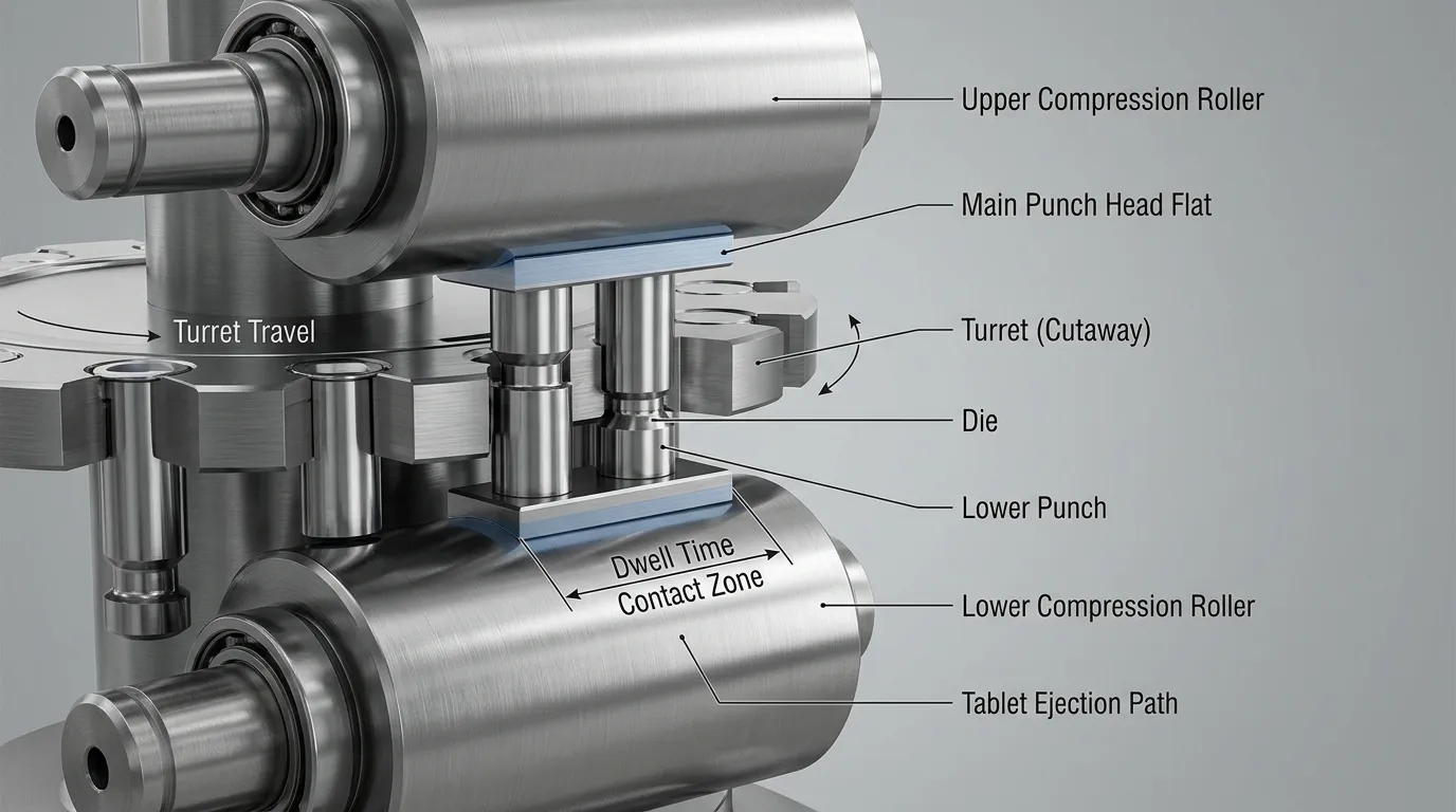
What the Punch Head Flat Changes During Tablet Compression
On a rotary tablet press, the upper and lower punch heads pass between the main compression rollers. As the rollers act on the punch heads, the punch tips move into the die and compact the powder bed.
The head flat is the relatively level section of the punch head that travels beneath the roller at the maximum-compression region. Its relevant dimension is the effective length in the direction of turret travel.
A longer effective flat keeps the punch near its minimum separation from the opposing punch for a greater travel distance. At an unchanged linear speed, that increases calculated dwell time.
This geometry is separate from the tablet-forming end of the punch. Cup depth, score lines, logos, and other face details belong to punch-tip design. Those adjacent decisions should be handled through separate tablet embossing design guidelines.
Geometric Dwell, Force-Based Dwell, and Consolidation Time Are Not Identical
The word dwell is not always used in the same way.
| Term | What it describes | Main variables |
|---|---|---|
| Geometric dwell time | Calculated time associated with the punch head flat passing through the maximum-compression region | Effective flat length and tangential velocity |
| Force-based dwell time | Dwell identified from the measured compression-force profile | Geometry, force level, formulation response, and measurement definition |
| Consolidation or compression time | A broader portion of the loading event during which the powder bed is being compressed | Roller profile, punch-head geometry, speed, displacement, and press behavior |
A 2024 peer-reviewed study comparing force-based and geometric dwell time found that measured dwell can vary with compression force and formulation even when the press geometry remains fixed.
For that reason, a geometric calculation is useful for equipment comparison and initial design work, but it should not be treated as a complete description of the tablet’s force-time history.
How to Calculate Geometric Dwell Time
A simplified geometric dwell calculation uses:
[
t = \frac{L}{v}
]
Where:
- (t) = geometric dwell time
- (L) = effective head-flat travel length
- (v) = tangential velocity at the punch position
Tangential velocity can be estimated from turret pitch circle diameter and rotational speed:
[
v = \frac{\pi \times PCD \times RPM}{60}
]
When PCD is expressed in millimetres, the result is millimetres per second. Dwell time in milliseconds is then:
[
t_{ms} = \frac{L}{v} \times 1000
]
Illustrative calculation
Assume:
- Effective flat length: 10 mm
- Turret PCD: 400 mm
- Turret speed: 30 RPM
Tangential velocity:
[
v = \frac{\pi \times 400 \times 30}{60}
]
[
v \approx 628.3\text{ mm/s}
]
Geometric dwell:
[
t = \frac{10}{628.3} \times 1000
]
[
t \approx 15.9\text{ ms}
]
This is an illustrative calculation, not a recommended dwell target. The actual tooling drawing, press geometry, roller arrangement, and operating conditions must be used for engineering decisions.
Use Effective Travel Length, Not a Generic Head Diameter
The complete punch-head diameter is not necessarily the correct dimension for dwell calculations.
For a round flat, the useful measurement is the flat dimension along the direction of turret travel. For an oval or elliptical flat, the long axis may be aligned with the travel direction to create more dwell without increasing the head equally in every direction.
The calculation should therefore use the effective travel length shown on the tooling drawing, not a generic head diameter taken from a catalogue or another press.
This distinction becomes especially important when comparing:
- Standard round flats
- Extended round flats
- Oval or elliptical flats
- Directional or keyed head designs
- Reduced flats used for shorter dwell conditions
Why RPM Alone Cannot Compare Two Tablet Presses
Two presses operating at 30 RPM can produce different dwell times if their turret pitch circle diameters differ.
A larger PCD means the punch travels a greater linear distance during each turret revolution. At the same RPM, it therefore has a higher tangential velocity and passes beneath the compression roller more quickly.
Press comparison should use at least:
- Turret RPM
- Pitch circle diameter
- Effective head-flat length
- Compression-roll geometry
Comparing RPM alone can create a false impression that development and production presses are operating under equivalent compression conditions.
Head-Flat Design Options and Their Dwell Trade-Offs
The appropriate head-flat design depends on the required dwell, press geometry, tooling standard, mechanical support, and formulation response.
| Head-flat design | Dwell effect | Potential benefit | Main limitation |
| Standard domed head | Baseline dwell for the press and tooling configuration | Conventional compatibility and established operation | May provide insufficient dwell for a highly rate-sensitive formulation |
| Extended round flat | Increases effective travel length | Longer geometric dwell without reducing turret speed | May reduce surrounding head geometry or create clearance and stress concerns |
| Oval or elliptical flat | Increases travel length mainly in one direction | Can create more dwell within a constrained head width | May require keying, orientation control, and additional wear assessment |
| Reduced flat | Shortens effective travel length | Can help a development press reproduce shorter production dwell | Less time at maximum compression and narrower operating margin |
Standard and Extended Round Flats
A standard domed punch head includes a flat surrounded by curved transition geometry. It provides the baseline dwell associated with the press speed, turret PCD, and standard tooling dimensions.
An extended round flat increases the flat region. At the same tangential velocity, this increases geometric dwell without slowing the turret.
The trade-off is that the flat cannot be enlarged without considering the rest of the head. Increasing it may reduce the available crown, outside radius, head thickness, or support above the punch neck. The design must still carry the compression load and pass safely through the press.
Oval, Elliptical, and Reduced Flats
An oval or elliptical head flat extends the contact path in the direction of turret travel while limiting growth across the head width. This can be useful where a full circular extension would interfere with surrounding press geometry.
Because the long axis must remain aligned with the travel direction, directional heads may require keyed tooling. Keying adds orientation control but can also affect interchangeability, setup, and localized wear.
A reduced flat serves the opposite purpose. It can shorten geometric dwell when a laboratory or development press naturally provides a longer dwell than the intended production machine.
How Dwell Interacts With Formulation Behavior and Tablet Quality
Head-flat geometry creates a time opportunity. The formulation determines what happens during that time.
Tablet materials can respond through several mechanisms:
- Plastic deformation: Particles change shape permanently, increasing contact area and supporting interparticle bonding.
- Elastic deformation: Particles recover after the load is removed, which can reduce retained bonding and increase residual stress.
- Viscoelastic behavior: Deformation depends on both time and loading rate.
- Brittle fragmentation: Particles fracture and create new bonding surfaces.
A slower loading event or longer dwell may support additional plastic flow in some formulations. Other materials may show little improvement, or the benefit may depend strongly on pressure, lubrication, moisture, particle size, and previous processing.
Research on extended dwell during tablet compression shows that material behavior must be evaluated under controlled conditions rather than predicted from head geometry alone. Earlier work on paracetamol and microcrystalline cellulose also found that dwell effects were linked with pressure history, recovery, and energy, not simply with a longer period beneath the roller.
Why Longer Dwell Does Not Guarantee a Stronger Tablet
Tablet strength depends on more than dwell. Relevant variables include:
- Compaction pressure
- Particle deformation mechanism
- Powder-bed porosity
- Lubricant concentration and mixing
- Moisture content
- Elastic recovery
- Loading and unloading rates
- Precompression conditions
A longer head flat may increase geometric dwell while the measured force plateau changes only slightly. Conversely, two formulations running with the same tooling may produce different force-based dwell profiles.
Breaking force and tensile strength also should not be treated as identical. Breaking force is a measured load, while tensile-strength calculations account for tablet dimensions and provide a more normalized comparison.
Capping and Lamination Are Multifactorial Problems
Capping and lamination are sometimes associated with inadequate dwell, but increasing the head flat is not a universal correction.
Possible contributors include:
- Air trapped in the powder bed
- Rapid force application
- Uneven densification
- Excessive elastic recovery
- Inadequate or excessive precompression
- Formulation or granulation properties
- Lubrication conditions
- Rapid decompression
- Tooling condition or alignment
A peer-reviewed investigation of force-application rate and tablet capping identified interactions among loading rate, trapped air, densification, and viscoelastic recovery.
Additional dwell may help a specific formulation, but it should be tested as one process variable within a broader root-cause study.
Mechanical Limits Before Extending a Punch Head Flat
A longer flat must remain mechanically sound and compatible with the press. The maximum useful flat is not determined by dwell requirements alone.
| Design issue | Possible consequence | Verification needed |
| Insufficient punch-neck support | Head deflection, stress concentration, or premature failure | Structural review of neck diameter and transition geometry |
| Reduced outside-head radius | Higher localized contact stress | Head-profile and roller-contact assessment |
| Excessive head width or length | Interference with cam tracks or adjacent press components | Full press-path clearance check |
| Directional oval geometry | Incorrect orientation beneath the roller | Keying and orientation-control review |
| Small or highly loaded contact region | Pitting, surface fatigue, or uneven wear | Contact-stress and material evaluation |
| Incompatible head thickness | Improper travel through cams or compression stations | OEM and tooling-standard comparison |
| Unverified roll interaction | Altered force application or edge loading | Compression-roll diameter and profile review |
Head Strength, Neck Support, and Contact Wear
The punch neck supports the head during compression. Extending the flat can reduce the surrounding curved geometry that transfers force from the roller into the neck.
Critical features include:
- Neck diameter
- Head thickness
- Transition radius
- Outside-head radius
- Contact position
- Material and heat-treatment condition
A sharper or smaller outside radius can increase contact stress between the head and compression roller. Repeated loading may then contribute to pitting, surface fatigue, or uneven wear.
These effects require engineering analysis for the actual punch and press. Generic maximum-flat dimensions should not be applied across different tooling standards or machine models.
Cam Tracks, Roll Geometry, and Keyed Orientation
The head must pass through the complete cam path, not only the main compression station. A design that works beneath the roller can still interfere with entry cams, exit cams, lifting tracks, or other press components.
Non-round flats add an orientation requirement. If the long axis must remain aligned with turret travel, a key or another rotation-control feature may be necessary.
Compression-roll geometry also matters. Roller diameter and profile influence the loading path before and after the nominal dwell region. A head-flat change therefore should be reviewed with the actual roll arrangement rather than evaluated as an isolated component.
Matching Dwell During Scale-Up and Press Transfer
Dwell comparison is often used when transferring a tablet from a development press to a production machine.
A useful comparison should collect:
- Turret pitch circle diameter
- Operating RPM range
- Effective upper and lower punch-head-flat dimensions
- Main and precompression-roll geometry
- Compression-force range
- Tablet thickness and dimensions
- Precompression conditions
- Formulation strain-rate sensitivity
- Press stiffness or deformation data where available
- Measured force and displacement profiles
The first calculation should compare tangential velocity and geometric dwell. It should then be checked against tablet properties and measured compaction behavior.
The principles in ICH Q8(R2) Pharmaceutical Development support building process understanding around material attributes and process parameters rather than relying on one isolated setting.
Matching Dwell Is Not the Same as Matching the Complete Compression Event
Two presses can have similar geometric dwell but different:
- Loading rates
- Roller radii
- Maximum forces
- Displacement profiles
- Press deformation
- Precompression histories
- Decompression rates
- Die-filling conditions
Matching dwell therefore does not guarantee identical tensile strength, porosity, dissolution behavior, or defect risk.
A compaction simulator can help reproduce selected force and displacement profiles under controlled conditions. It is useful for studying formulation sensitivity and planning scale-up, but production-press verification is still required.
Which Adjustment Should Be Used to Change Dwell Conditions?
The best intervention depends on the problem being solved.
| Adjustment | Best used when | Advantage | Limitation |
| Reduce turret speed | Testing whether the formulation is rate-sensitive | Simple process trial | Reduces output and may change other press conditions |
| Extend or reshape the head flat | More geometric dwell is needed without lowering nominal turret speed | Maintains speed potential | Requires new tooling and full compatibility review |
| Change compression-roll geometry | The broader consolidation profile needs adjustment | Can alter loading and unloading behavior | Press-dependent and may require machine modification |
| Use a compaction simulator | Development or scale-up conditions need controlled evaluation | Allows repeatable force-profile studies | Does not replace production validation |
| Adjust formulation or precompression | The root cause is material behavior, air, lubrication, or densification | Addresses the underlying mechanism | Requires pharmaceutical development and change control |
A practical sequence is to test speed sensitivity first, because a controlled speed reduction can show whether more time under compression improves the formulation. If it does, engineers can evaluate whether modified head geometry, different roll conditions, or formulation work offers the most suitable production solution.
Data to Confirm Before Specifying a Different Head Flat
A request for “more dwell” is not enough for a tooling designer. The specification should include:
- Tablet press make and model
- Applicable tooling standard
- Current upper and lower punch drawings
- Existing head-flat dimensions
- Desired effective travel direction
- Turret pitch circle diameter
- Normal and maximum operating RPM
- Main and precompression-roll details
- Compression-force range
- Cam-track clearance information
- Punch-neck dimensions
- Keying or rotation-control requirements
- Tablet dimensions and target properties
- Development and production press data
- Formulation sensitivity or compaction-study results
- Inspection and traceability requirements
- Proposed validation method
Current dimensional requirements should be checked against the applicable standard and press documentation. The American Pharmacists Association’s Tableting Specification Manual is a current North American reference for tablet-tooling terminology, design, and interchangeability. Other tooling systems may require different standards and OEM requirements.
Questions to Ask the Press OEM or Tooling Supplier
Before approving a modified head, confirm:
- Will it pass safely through every cam track?
- Does the punch neck provide enough structural support?
- Will the head contact the compression roll as intended?
- Does the design require a key or controlled orientation?
- Which current standard governs the dimensions?
- How will flat length, profile, and orientation be inspected?
- What contact-stress or wear evaluation is required?
- Will the tooling remain interchangeable with existing sets?
- How should the new design be validated on the intended press?
- What material, heat-treatment, coating, and traceability documentation will be supplied?
Use Head-Flat Changes as a Controlled Engineering Decision
Tablet punch head flat and dwell time are directly related at the geometric level: a longer effective flat increases dwell when tangential velocity remains unchanged. That calculation is useful, but it does not predict tablet performance by itself.
A defensible design decision combines geometric dwell, measured compaction behavior, formulation response, mechanical strength, cam compatibility, roll geometry, and current tooling requirements. Calculate first, test the formulation, verify the press constraints, and compare alternative interventions before approving a modified punch head.
Share:


Written By Tonmoy
NEWS
GET SERVICE
With quality parts to meet every budget and friendly staff trained to make your visit informative and hassle free.
