



Carbide vs Tool Steel Punch Pins: Tool Life, Risk, and Cost
Carbide does not automatically make a better punch pin, and tool steel is not always the cheaper long-term choice. Carbide is usually the stronger candidate when gradual abrasive wear, dimensional drift, and frequent sharpening limit production. Tool steel is often safer when the punch faces impact, bending, side loading, uncertain alignment, or frequent design changes.
The right choice depends on how the current punch fails and how much that failure costs. Material selection is only one part of the wider die decision covered in this punching dies guide (inferred). Here, the focus is narrower: selecting between cemented-carbide and tool-steel punch pins based on tool life, breakage risk, maintenance, and cost per accepted part.
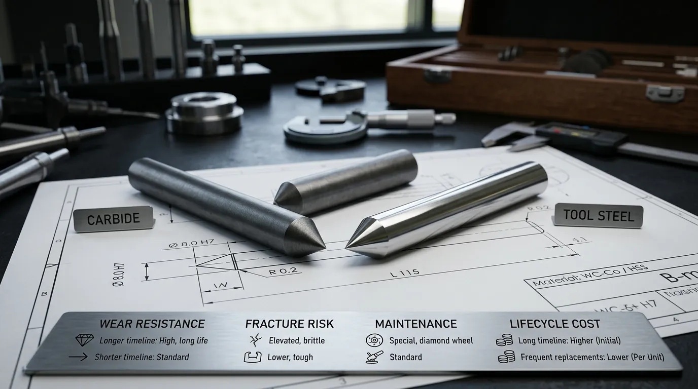
Carbide vs Tool Steel Punch Pins at a Glance
| Comparison factor | Cemented carbide punch pin | Tool-steel punch pin |
|---|---|---|
| Wear resistance | Usually higher, especially in abrasive and stable applications | Depends heavily on the steel grade and heat treatment |
| Edge retention | Can maintain dimensions and cutting-edge condition for longer when wear controls failure | May require more frequent sharpening in severe wear conditions |
| Chipping and fracture tolerance | More sensitive to impact, side loading, and stress concentration | Generally more forgiving under shock, bending, and unstable conditions |
| Alignment requirements | Requires accurate guidance, support, and uniform clearance | Usually tolerates minor operating variation better |
| Geometry suitability | Risk increases with slender sections, unsupported length, and abrupt transitions | Often preferred for difficult or deflection-prone geometries |
| Regrinding | Possible, but normally requires suitable diamond-grinding equipment and experience | Generally easier for a conventional toolroom to regrind or modify |
| Initial cost | Usually higher | Usually lower, though premium HSS and PM grades can narrow the difference |
| Best-fit use | Stable, repetitive, wear-dominated production | Impact-prone, changeable, short-run, or fracture-sensitive production |
| Economic test | Reduced service interruptions must justify the higher purchase and maintenance cost | Lower acquisition and easier maintenance must offset shorter service intervals |
These are directional differences, not guaranteed outcomes. Carbide grade, steel grade, punch geometry, workpiece material, die condition, clearance, lubrication, and maintenance practices can change the result.
What “Carbide” and “Tool Steel” Mean in This Comparison
The comparison is between punch pins made from cemented tungsten carbide and punches made from hardened tool steel. A steel punch with a thin surface coating is not the same as a solid or predominantly carbide punch.
The term “tool steel” also covers several material families. A conventional D2- or SKD11-type punch does not offer the same performance balance as high-speed steel or a powder-metallurgy tool steel.
Cemented Carbide Is a Grade Family, Not One Fixed Material
Cemented carbide is a composite material. Hard tungsten-carbide particles provide much of its hardness and wear resistance, while a metallic binder holds those particles together and contributes toughness.
According to CERATIZIT’s technical explanation of cemented carbide, binder content and carbide grain size are two major variables controlling material properties. This means that specifying only “tungsten carbide” is incomplete.
A grade selected for maximum wear resistance may not provide the best resistance to chipping. A tougher carbide grade may survive impact or interrupted loading better, but it may not retain its edge as long in a purely abrasive application.
A responsible carbide specification should therefore consider:
- Binder content
- Carbide grain-size class
- Required wear resistance
- Expected shock and bending load
- Punch cross-section and unsupported length
- Workpiece material and surface condition
Tool Steel Includes Conventional, HSS, and PM Options
Tool steel should not be treated as one low-cost, low-performance category.
Conventional cold-work grades such as D2 or SKD11 are widely associated with good abrasive wear resistance and compressive strength. They can work well where loads are controlled and the geometry is sufficiently supported. Their suitability becomes less certain when severe chipping or shock resistance is required.
High-speed steel, including M2- or SKH51-type grades, is also part of the tool-steel family. It generally offers a different balance of wear resistance, toughness, and regrindability from conventional cold-work steel.
Powder-metallurgy tool steels can provide another intermediate option. Their finer and more uniform structure may improve the balance between wear resistance and toughness compared with conventional grades. The AHSS Guidelines discussion of tooling and die wear notes that tool selection must account for wear, shock resistance, stiffness, toughness, and the actual forming or cutting conditions.
Heat treatment remains critical for every steel option. The grade name alone does not establish final punch performance.
Which Material Delivers Longer Punch-Pin Life?
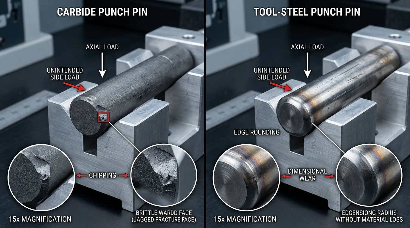
Carbide can deliver a much longer service interval when abrasive wear is the main reason the punch leaves production. It may not last longer when the real problem is chipping, cracking, bending, misalignment, or unstable stripping.
Tool life should therefore be connected to a defined failure mode rather than a generic number of strokes.
Carbide Has the Strongest Case When Wear Controls Failure
Carbide is a strong candidate when the punch gradually loses its cutting profile instead of breaking suddenly.
Typical wear-dominated symptoms include:
- Progressive edge rounding
- Increasing burr height
- Gradual hole-size or feature drift
- Frequent scheduled sharpening
- Surface wear without major edge chipping
- Consistent failure after similar production intervals
These conditions allow carbide’s wear resistance to create measurable value. The benefit may appear as longer intervals between service, more stable dimensions, fewer tool changes, or lower inspection and adjustment demand.
The application must still be mechanically stable. High wear resistance cannot compensate for uneven clearance, poor guidance, or a punch that bends during entry.
Tool Steel May Last Longer When Fracture Controls Failure
A tool-steel punch may be more reliable when sudden damage ends the tool’s service life.
Warning signs include:
- Chipped cutting edges
- Cracks near a diameter change
- Complete punch fracture
- Repeated bending or deflection
- Uneven wear on one side
- Damage during withdrawal from the sheet
- Failures that occur at inconsistent intervals
In these conditions, additional hardness may not solve the problem. The punch may need greater toughness, improved support, corrected alignment, a different transition radius, or a revised stripper arrangement.
Material-related fracture is only one part of the diagnosis. The dedicated guide to punch breakage in stamping dies covers the wider causes and corrective actions.
Define Tool Life Before Comparing Materials
“Longer life” has little meaning unless the endpoint is defined.
Possible endpoints include:
- Maximum acceptable burr
- Hole diameter or profile tolerance
- Surface-defect limit
- First visible edge chip
- Catastrophic breakage
- Scheduled sharpening interval
- Number of accepted parts before service
Accepted parts are usually a better comparison measure than raw press strokes. A punch may complete many strokes while producing parts that no longer meet the drawing or burr requirement.
The same endpoint must be used for both materials. Comparing a steel punch until sharpening with a carbide punch until complete fracture produces a misleading result.
Why Carbide Can Last Longer—or Break Earlier
Carbide performs best when the die system keeps the punch under controlled, predominantly axial loading. Its wear advantage becomes less useful when the punch is exposed to bending, uneven contact, or sudden impact.
Alignment, Clearance, and Guide Condition
A punch should enter the die opening concentrically. Worn guide posts, loose bushings, plate movement, holder runout, or uneven clearance can move the load toward one side of the cutting edge.
That local load increases stress even when the average punching force appears acceptable. A steel punch may deflect or wear under these conditions. A carbide punch may chip or fracture with less visible warning.
SunshinePro’s die components guide explains how punches, guide posts, bushings, wear components, and stripper systems interact. These components should be inspected before a steel punch is replaced with carbide.
Clearance also matters. Insufficient, excessive, or uneven punch-to-die clearance can change cutting force, burr formation, material flow, and edge loading. Carbide should not be used to hide a clearance problem.
Punch Geometry, Stripping, and Workpiece Conditions
Geometry strongly affects risk. A small-diameter punch with a long unsupported section is more sensitive to bending than a short, well-supported punch of the same material.
Risk can also increase with:
- Abrupt diameter changes
- Sharp internal transitions
- Insufficient head or shoulder support
- Uneven cutting-edge geometry
- High stripping force
- Material lifting during punch withdrawal
- Slug pulling
- Off-centre contact with the sheet
The workpiece changes the loading environment as well. Strength, thickness, coating, surface roughness, and abrasive particles can affect cutting force and wear. The AHSS Guidelines identifies tool material, contact pressure, sheet strength, surface condition, coating, lubrication, temperature, and sliding behavior as interacting wear variables.
This is why a material that performs well in one die may fail quickly in another, even when the punch dimensions look similar.
How to Compare Cost per Accepted Part
Carbide normally costs more to purchase, but initial price alone does not show which material is more economical.
A useful comparison includes every cost directly influenced by the punch:
- Initial punch purchase
- Regrinding or sharpening
- Coating or recoating, where applicable
- Replacement tools
- Removal and installation labor
- Setup and adjustment time
- Press downtime
- Scrap produced before a worn or damaged punch is detected
- Additional inspection
- Emergency maintenance
- Accepted production output
A basic calculation is:
Cost per accepted part = Total punch-related cost ÷ Number of accepted parts produced
For example, two punches may have very different purchase prices. The more expensive punch can still cost less per part if it reduces planned service, emergency stoppages, scrap, and adjustment time. The cheaper punch can remain the better choice when production demand is limited, maintenance is simple, or carbide fracture risk is high.
The calculation should use actual plant data where possible. Avoid assuming that carbide will last five, ten, or twenty times longer. Such multipliers cannot be transferred reliably between different workpiece materials, punch geometries, presses, clearances, and failure criteria.
A risk-adjusted comparison should model at least two carbide outcomes:
- Expected case: Carbide reaches the planned wear-based service interval.
- Adverse case: Carbide chips or breaks early because of side loading, impact, or an unsuitable grade.
This prevents a favourable wear estimate from hiding the financial effect of one catastrophic failure.
When to Choose Carbide, Tool Steel, or a Middle Option
| Production condition | Stronger starting candidate | Main reason |
| Stable die, abrasive wear, frequent sharpening | Carbide | Wear resistance may extend service intervals |
| Repeated chipping, bending, or impact | Tougher tool steel | Fracture resistance matters more than maximum hardness |
| Short production run or changing part design | Tool steel | Lower initial commitment and easier modification |
| Long repetitive run with costly downtime | Carbide, after system checks | Reduced intervention may justify the higher cost |
| Conventional steel wears too quickly, but carbide risk is high | HSS or PM tool steel | Intermediate wear–toughness balance |
| Different stations show different failure modes | Hybrid material strategy | Each station can use the material suited to its load |
Choose Carbide When Wear and Downtime Dominate
Carbide is a strong candidate when:
- The existing punch wears gradually rather than breaking.
- Guidance and clearance are stable.
- Punch geometry is well supported.
- The workpiece creates significant abrasive wear.
- Repeated sharpening interrupts valuable production time.
- Dimensional consistency between service intervals is important.
- A suitable carbide grade can be selected.
- Qualified carbide grinding and handling are available.
High production volume strengthens the economic case, but volume alone is not enough. A high-volume die with poor alignment can consume carbide punches faster than a well-selected steel alternative.
Choose Tool Steel When Toughness and Flexibility Dominate
Tool steel is often the safer choice when:
- The punch experiences impact or side loading.
- Geometry is slender or difficult to support.
- Alignment cannot be controlled closely.
- The die is used for prototypes, short runs, or changing designs.
- The punch may need local modification.
- In-house regrinding is important.
- A sudden carbide fracture could damage other die components.
- Current failures are cracks or chips rather than gradual wear.
The exact grade still matters. Conventional cold-work steel, HSS, and PM tool steel should not be grouped under one performance assumption.
Consider HSS, PM Tool Steel, or a Hybrid Die Strategy
The decision does not always need to be binary.
HSS may provide more wear resistance than a conventional tool steel while retaining useful toughness and easier regrinding than carbide. PM tool steel may offer another balance where both wear and chipping are concerns.
A hybrid die can also use different materials in different stations. Carbide may be justified at stable, high-wear piercing stations, while a tougher steel remains preferable where punches are slender, heavily stripped, or exposed to off-axis load.
Testing one high-wear station before converting a complete punch set can reduce technical and financial risk.
Check the Die System Before Upgrading to Carbide
Before replacing a steel punch with carbide, verify the following:
- Identify the present failure mode. Determine whether the punch wears, deforms, chips, cracks, bends, or breaks.
- Inspect the guide system. Check guide posts, bushings, plates, and holders for movement or uneven wear.
- Verify alignment and runout. Confirm that the punch enters the die opening concentrically.
- Check clearance around the full cutting perimeter. Do not rely on one measurement.
- Review punch support. Examine unsupported length, head support, diameter changes, and transition radii.
- Evaluate stripping conditions. Look for excessive stripping force, material lifting, or slug pulling.
- Confirm workpiece details. Record material grade, strength condition, thickness, coating, and lubrication.
- Review the maintenance process. Confirm that appropriate carbide grinding, inspection, and handling are available.
- Set a success criterion. Define the required burr, dimensional limit, service interval, and accepted-part target.
If these checks reveal a mechanical problem, correct it before changing material. A carbide upgrade should address a wear problem, not conceal a die-system fault.
What to Send a Supplier for a Responsible Material Recommendation
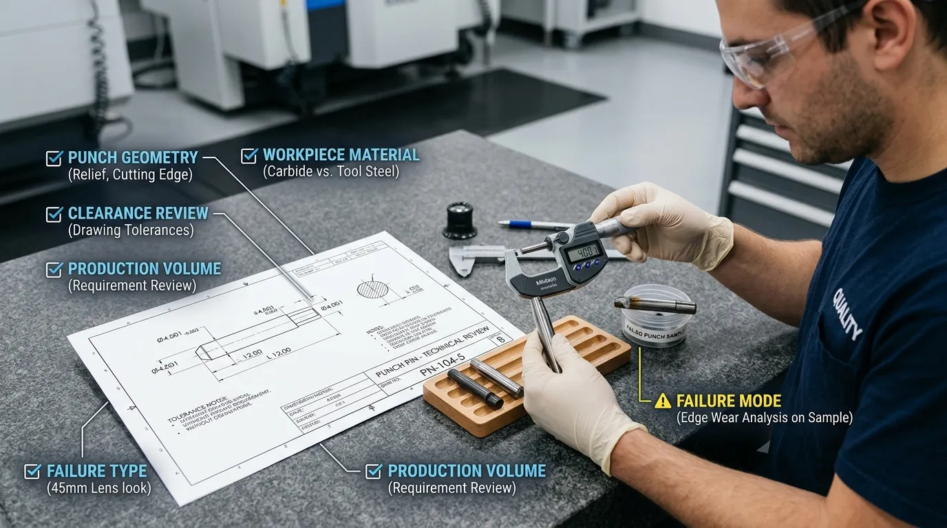
A supplier cannot make a defensible carbide-versus-tool-steel recommendation from the punch diameter alone.
Provide:
- Dimensioned punch drawing or physical sample
- Punch diameter, length, head style, and transition geometry
- Required tolerances and surface requirements
- Workpiece material and grade
- Workpiece thickness and strength condition
- Surface coating or plating
- Press type and operating speed, where relevant
- Punch-to-die clearance
- Lubrication conditions
- Stripper arrangement
- Expected annual or batch volume
- Current punch material and heat treatment
- Current service interval
- Regrinding history
- Photographs of worn or broken punches
- Description of the failure mode
- Acceptable burr and dimensional limits
- Downtime or changeover impact
SunshinePro lists carbide punches, die punch pins, and high-speed steel punches within its punching dies and pins range. Its carbide punch information also lists grinding, EDM, precision machining, custom dimensions, and selected coating options. The exact material grade, geometry, tolerance, coating, and process route still need confirmation against the drawing and application.
Final Decision Rule: Match the Material to the Failure Mode
Choose carbide when controlled alignment and stable geometry allow wear resistance to reduce service interruptions and cost per accepted part. Choose tool steel when toughness, repairability, geometry, or fracture control matters more than maximum wear resistance. Consider HSS or PM tool steel when the application falls between those positions.
The most reliable decision starts with the failed punch, the die condition, and the production data—not with hardness alone. To evaluate a custom requirement, send the punch drawing, workpiece details, operating conditions, and failure history through SunshinePro’s contact page.
Share:


Written By Tonmoy
NEWS
GET SERVICE
With quality parts to meet every budget and friendly staff trained to make your visit informative and hassle free.
