



Mold Positioning Pin Tolerance for Repeatable Alignment
There is no single mold positioning pin tolerance that works for every mold. Repeatable alignment depends on a complete tolerance chain: the pin diameter, the mating hole or bushing diameter, the fit between them, the position and orientation of both features, and the dimensional changes that occur during operation.
A pin can be ground to a very tight diameter tolerance and still fail to locate the mold correctly if its hole is misplaced, its axis is tilted, or two locating pins create an overconstrained pattern. For broader guidance on guide systems, wear, and fit selection, see mold pins and bushings (inferred). This guide focuses specifically on defining, calculating, documenting, and inspecting positioning-pin tolerances.
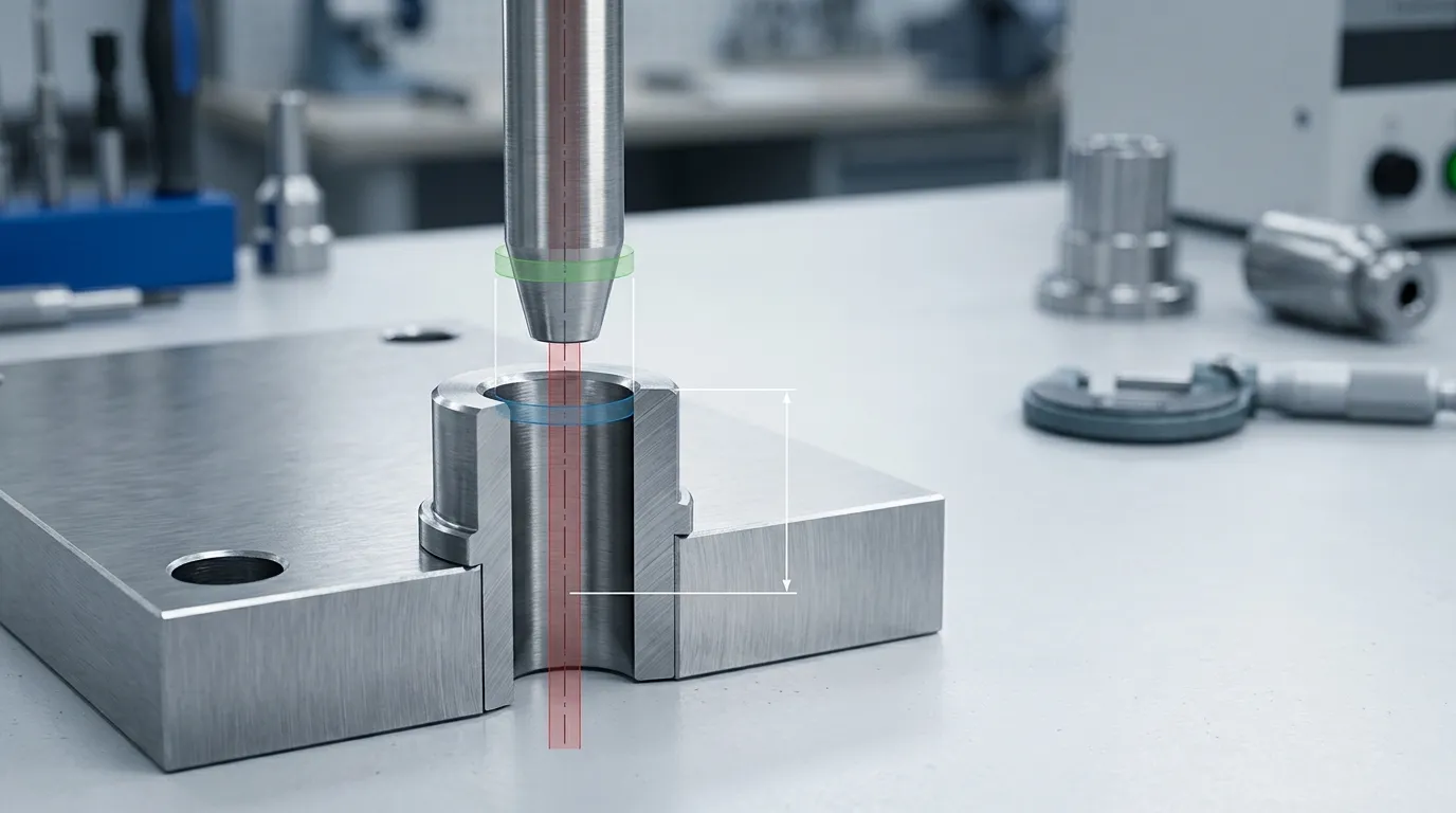
What Does a Mold Positioning Pin Tolerance Actually Control?
The word “tolerance” may refer to several different requirements. These controls are related, but they are not interchangeable.
| Control | What It Defines | What It Does Not Define |
|---|---|---|
| Pin size tolerance | The largest and smallest acceptable pin diameter | The position of the pin axis |
| Hole or bushing tolerance | The largest and smallest acceptable mating bore | Whether the bore is correctly located |
| Pin-to-hole fit | The possible clearance or interference between the two features | Total mold alignment error |
| Geometric tolerance | The permitted position and orientation of the pin or hole axis | The actual clearance between the parts |
| System repeatability | How consistently the mold returns to the same position | Whether that repeated position is the correct nominal position |
The ISO 286-1 system of limits and fits defines size tolerances and fit relationships for holes and shafts. It does not control where a hole is located or whether its axis is perpendicular to the mold plate. Those requirements need geometric controls, such as those defined by ISO 1101.
Size Tolerance, Fit, and Alignment Are Different Requirements
Suppose a positioning pin and its mating hole are both within their specified diameter limits. That confirms only that their sizes are acceptable.
It does not confirm that:
- the pin and hole centers coincide;
- their axes are parallel;
- two locating holes have the correct spacing;
- the mold returns to its intended position;
- the assembly will still engage after heating or wear.
The actual fit comes from the combination of both size ranges. The smallest permitted hole paired with the largest permitted pin creates the tightest possible assembly. The largest hole paired with the smallest pin creates the loosest possible assembly.
Both extremes must be checked.
Position, Orientation, and Repeatability Complete the Specification
A bore may have the correct diameter but still be offset from its basic location. A pin may be positioned correctly at the plate surface but tilted enough to bind over a long engagement length.
A complete positioning specification may therefore need:
- a functional datum reference frame;
- basic dimensions locating the pin or hole;
- positional tolerance;
- perpendicularity or another orientation control;
- pattern control for multiple locating features.
Repeatability and accuracy should also be distinguished. Repeatability describes how consistently the mold returns to the same position. Accuracy describes how close that position is to the intended nominal location.
A locating system can be repeatable but consistently offset if the feature pattern was manufactured in the wrong position.
Positioning pins should not automatically be treated as equivalent to mold guide pins. Guide pins primarily control movement as mold halves open and close. A dedicated positioning pin may establish a more precise final location after the mold halves approach engagement.
Define the Functional Requirement Before Selecting the Fit
A tolerance should start with the required function, not with a familiar fit designation.
Before assigning limits, define:
- The maximum permitted translational alignment error.
- The maximum permitted angular error.
- The nominal pin diameter and engagement length.
- Whether the pin is permanent, removable, or replaceable.
- How often the mold will be assembled or disassembled.
- Which side retains the pin.
- Which side provides the locating engagement.
- The operating temperature range.
- The expected wear, lubrication, and contamination conditions.
- The manufacturing and inspection methods available.
- Whether binding or excess clearance creates the greater functional risk.
A positioning system used for a removable insert may prioritize easy engagement and interchangeability. A permanently installed locator may require stronger retention on its mounting side. A heated mold may need enough room for differential thermal expansion between the pin, bushing, and mold plate.
Application labels alone do not determine the correct fit. An “automotive mold” or “medical mold” still needs a defined alignment requirement, material combination, temperature range, and inspection plan.
Separate the Fixed Interface from the Locating Interface
The two ends of a positioning pin usually perform different jobs.
| Interface | Primary Function | Possible Fit Direction |
| Mounting side | Retain the pin in the supporting plate and preserve its axis | Controlled transition or interference, depending on design |
| Locating side | Enter the mating hole or bushing and limit relative movement | Controlled clearance or transition, depending on function |
Using the same fit on both sides can create avoidable problems. A locating-side interference fit may prevent normal assembly. Excessive mounting-side clearance may allow the pin to shift or loosen.
The final selection must also consider plate thickness, surrounding material, removal method, replacement needs, and the risk of distortion during installation.
Choose the Fit and Calculate the Actual Clearance
Clearance, transition, and interference fits describe the relationship between the complete pin and hole tolerance zones.
Clearance, Transition, and Interference Serve Different Functions
| Fit Type | Dimensional Result | Typical Functional Use | Main Risk |
| Clearance fit | The smallest hole remains larger than the largest pin | Sliding or removable locating engagement | Excess movement if clearance is too large |
| Transition fit | Some valid combinations have clearance; others have interference | Close location or moderate retention | Variable assembly force |
| Interference fit | The smallest pin remains larger than the largest hole | Permanent or semi-permanent retention | Distortion, difficult removal, or installation damage |
These categories describe outcomes, not universal recommendations. A clearance fit may be suitable on the locating side while an interference or transition fit is used on the mounting side.
The hole-basis system is common because standard hole-making tools can establish a defined hole tolerance while the shaft or pin tolerance is selected to create the required fit. Still, a designation such as H7/g6 or H7/m6 is incomplete without the nominal diameter and governing standard. The numerical deviations change across diameter ranges.
Use Limit Dimensions to Check Both Assembly Extremes
Calculate the limits before approving the fit.
Minimum clearance
Minimum clearance = Smallest permitted hole − Largest permitted pinMaximum clearance
Maximum clearance = Largest permitted hole − Smallest permitted pinA negative result represents interference.
Consider a hypothetical example:
| Feature | Minimum Diameter | Maximum Diameter |
| Locating hole | 10.010 mm | 10.018 mm |
| Positioning pin | 9.998 mm | 10.004 mm |
The tightest possible assembly is:
10.010 − 10.004 = 0.006 mm minimum diametral clearanceThe loosest possible assembly is:
10.018 − 9.998 = 0.020 mm maximum diametral clearanceThese values are examples only. They are not recommended SunshinePro specifications or universal mold tolerances.
Diametral clearance also should not be treated as the complete alignment error. In an ideal single-pin interface, the pin center may move radially by up to approximately half the diametral clearance before contact. The actual mold position also depends on the second locator, feature positions, axis angles, engagement lengths, deformation, and operating conditions.
Control the Locating Pattern, Not Only the Pin Diameter
A precision fit cannot compensate for an incorrectly located pattern.
The pin and mating feature must be controlled from datums that represent how the mold is assembled and functions. These may include a seating face, a side reference, or another stable mold-base feature.
Use Functional Datums, Position, and Axis Control
A practical drawing should identify:
- the surfaces establishing the functional datum reference frame;
- the basic locations of the pin and mating hole;
- the permitted positional variation;
- any required perpendicularity or axis-orientation control;
- the relationship between multiple locating features.
ISO 5458 provides complementary rules for pattern specifications under the ISO GPS system. Drawings using ASME conventions should follow ASME Y14.5.
The drawing should clearly use one governing convention. Mixing ISO and ASME symbols or assumptions without clarification can create conflicting interpretations between the designer, manufacturer, and inspector.
Avoid Overconstraint with a Round and Relieved Pin Pair
Two fully round pins entering two close-fitting round holes can overconstrain the assembly.
For both pins to engage, the distance between the pins must agree closely with the distance between the mating holes. Even when every individual diameter is acceptable, accumulated spacing and position variation can cause binding.
A common locating arrangement uses:
- one round pin as the primary locator;
- one diamond, relieved, or flattened pin as the secondary locator.
The round pin controls movement in two planar directions. The relieved pin controls the required secondary direction while allowing some variation along the relieved axis.
The secondary pin must be oriented correctly. Rotating its relieved direction by 90 degrees changes which movement it permits and which movement it controls.
Locator spacing also affects angular definition. Greater spacing can reduce angular movement for a given amount of linear clearance, but no universal spacing rule applies. Plate size, loads, available space, hole-position capability, and engagement geometry still need evaluation.
Build a Worst-Case Tolerance Stack for Repeatable Alignment
The fit calculation covers only one part of the positioning system. A complete tolerance budget should include every variation capable of moving, tilting, or preventing engagement between the mold halves.
Typical contributors include:
| Contributor | Possible Effect |
| Pin diameter | Changes clearance or interference |
| Hole or bushing bore | Changes clearance or interference |
| Pin mounting position | Moves the locator axis |
| Mating-hole position | Moves the receiving axis |
| Axis orientation | Creates angular mismatch or edge contact |
| Bushing outside-diameter fit | Allows or restricts bushing movement |
| Bore-to-outside relationship | Offsets the functional bushing bore |
| Pin-pattern spacing | Affects simultaneous engagement |
| Mold-plate temperature | Changes component dimensions |
| Wear | Increases effective clearance |
| Debris | Reduces usable clearance or prevents full seating |
| Measurement uncertainty | Reduces confidence in the acceptance decision |
A practical worst-case process is:
- Define the maximum permitted alignment variation.
- Identify each dimensional and geometric contributor.
- Calculate the tightest and loosest component fits.
- Add the possible positional and orientation effects.
- Check whether every permissible combination can assemble.
- Reserve allowance for operating temperature, wear, and contamination.
- Confirm that the inspection system can verify the specified limits.
Worst-case analysis is appropriate when assembly must be guaranteed at every permitted limit. Statistical tolerance analysis may be useful in established, capable production processes, but it should not replace functional verification without a justified process model.
Separate Manufacturing Variation from Operating Variation
Manufacturing variation includes:
- component diameter;
- hole diameter;
- feature position;
- perpendicularity;
- pattern spacing;
- bushing installation position.
Operating variation includes:
- thermal expansion;
- wear;
- debris;
- lubrication condition;
- plate movement or deformation.
A fit that works during inspection at room temperature may become too tight after heating. A fit that begins with acceptable clearance may lose repeatability as the pin or bushing wears.
Lubrication can reduce friction and seizure risk, but it cannot correct an invalid tolerance stack. Material and hardness affect how well the components retain their dimensions over time, but those decisions should remain separate from the basic fit calculation.
Use a Hypothetical Stack to Test the Design
Assume a design permits 0.030 mm of total lateral variation at a functional location.
A simplified hypothetical budget might allocate:
| Contributor | Permitted Effect |
| Pin-to-bushing radial movement | 0.008 mm |
| Pin position variation | 0.006 mm |
| Bushing position variation | 0.006 mm |
| Orientation and engagement effect | 0.004 mm |
| Temperature and wear allowance | 0.004 mm |
| Remaining design margin | 0.002 mm |
If the calculated worst-case total exceeds 0.030 mm, the design must change. Possible actions include:
- reducing maximum clearance;
- improving positional control;
- increasing locator spacing;
- using a replaceable bushing;
- revising the relieved-pin geometry;
- reducing operating variation;
- redefining the functional requirement.
The example demonstrates the budgeting method only. Real values must come from the mold’s geometry, operating conditions, and manufacturing capability.
Specify the Requirement Clearly on the Drawing or RFQ
A supplier cannot reliably manufacture or inspect an ambiguous precision requirement.
The drawing or request for quotation should identify:
- nominal pin, hole, and bushing dimensions;
- limit dimensions or an unambiguous fit designation;
- the governing tolerance standard;
- separate mounting-side and locating-side requirements;
- functional datums;
- basic feature locations;
- position and orientation tolerances;
- primary and secondary locator roles;
- the orientation of any relieved or flattened pin;
- material and hardness where functionally necessary;
- heat-treatment condition;
- surface finish on locating diameters;
- operating temperature assumptions;
- whether components must be interchangeable;
- whether selective assembly is permitted;
- required inspection characteristics;
- required inspection records;
- whether pins and bushings are supplied as matched components.
The supplier should also know which characteristics are function-critical. A tight pin diameter may be less valuable than a slightly wider size tolerance combined with better positional control.
Avoid Ambiguous Precision Notes
Specifications that need clarification include:
- “high-precision pin” without dimensional limits;
- “±0.005 mm” without naming the controlled feature;
- an ISO fit class without a nominal diameter;
- pin diameter tolerance without a mating-hole tolerance;
- diameter controls without feature-position controls;
- room-temperature dimensions without relevant operating conditions;
- a tolerance with no defined inspection method;
- “100% inspection” without identifying the inspected characteristics.
A numerical tolerance has meaning only when the feature, datum, standard, conditions, and measurement method are clear.
Verify the Pin, Hole, Pattern, and Assembly
Inspection should follow the structure of the specification.
| Controlled Requirement | Suitable Verification Direction |
| Pin diameter | Measure at defined locations and orientations |
| Hole or bushing diameter | Verify bore limits with an appropriate calibrated method |
| Pin or hole position | Measure relative to the stated datum reference frame |
| Axis orientation | Verify perpendicularity or angular relationship |
| Pattern spacing | Measure the relationship between locating features |
| Complete engagement | Use a controlled assembly check or functional gauge where appropriate |
| Repeatability | Test repeated assembly under defined conditions |
No single measurement verifies every requirement.
A micrometer may confirm a pin diameter but cannot establish the pin’s position in the mold plate. A bore measurement may confirm hole size but not perpendicularity. A functional gauge may show that the current assembly engages, but it may not identify which individual feature is approaching its tolerance limit.
The inspection plan should also consider:
- instrument resolution;
- calibration status;
- fixturing;
- measurement temperature;
- accessibility of the feature;
- measurement uncertainty.
If the measurement uncertainty is too large relative to the tolerance, the conformity decision becomes unreliable. Component conformity also does not automatically prove long-term repeatability under heat, wear, and repeated mold cycles.
Decide Whether a Standard Component or Custom Tolerance Is Needed
A standard pin or bushing is suitable when its published dimensions, tolerance class, geometry, material, and mounting configuration satisfy the calculated tolerance stack.
Customization may be justified when the design requires:
- a non-standard diameter or locating length;
- separate mounting and locating diameters;
- a special shoulder or flange;
- a defined relieved-pin orientation;
- a specific material or hardness;
- a controlled surface finish;
- unusual retention or removal features;
- a tolerance not available in a standard series.
The decision should start with the functional requirement rather than an assumption that custom parts are automatically more precise. A custom pin still depends on the mating hole, bushing, datum system, and inspection method.
SunshinePro states that it supplies mold components and supports non-standard accessories based on drawings or samples. Its locating pin guide bushing page lists straight, flanged, and custom structures, along with standard or customized sizes. Buyers comparing catalog and drawing-based options can also review the broader guidance on mold standard parts.
Before ordering, confirm which feature the supplier’s stated tolerance applies to, how it will be inspected, and whether the component must be interchangeable with other pins or bushings.
For a drawing-based review, provide the pin and mating-feature limits, datum scheme, required fit, operating conditions, material or hardness requirements, and inspection expectations through the SunshinePro contact page.
Share:


Written By Tonmoy
NEWS
GET SERVICE
With quality parts to meet every budget and friendly staff trained to make your visit informative and hassle free.
