



Punch Pin Coatings for Stamping Dies: Selection by Wear Mode
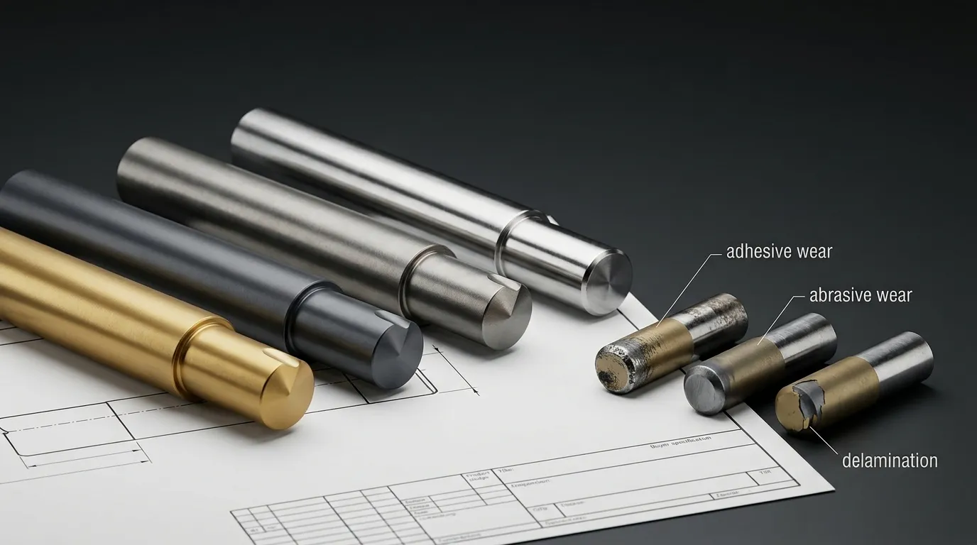
There is no universally best coating for a stamping-die punch. The correct choice depends on why the punch is wearing, what material it contacts, how the punch is supported, and whether the die setup is mechanically sound.
Start by identifying the wear mode. Then correct clearance, alignment, substrate, edge, finish, or lubrication problems that a thin coating cannot solve. Only after that should you compare coating families such as TiN, TiCN, CrN, DLC, TiAlN, or AlCrN.
For broader guidance on die types, punch materials, clearance, tolerances, and sourcing, see the punching dies guide (inferred). This guide focuses specifically on selecting punch pin coatings for stamping dies.
Start With the Punch’s Actual Wear Pattern
A damaged punch surface does not automatically reveal the root cause. Deposited workpiece material can cover the original surface, while a chipped coating may hide deformation or cracking in the substrate below it.
Before selecting another coating, record:
- Where the damage appears
- Whether it is uniform or one-sided
- Whether material has transferred onto the punch
- Whether the cutting edge is rounded, chipped, cracked, or deformed
- How the damage changes with production time
- Whether burr height, stripping force, or part finish changes at the same time
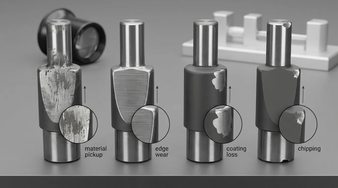
Use photographs, dimensional records, production counts, and failed samples where practical. Standardized terminology such as that in ASTM G40 can help distinguish wear categories, but the visible symptoms still need to be interpreted in the context of the stamping operation.
| Observed condition | Probable failure category | What to investigate first |
|---|---|---|
| Smearing, transferred material, local deposits, or scoring | Adhesive wear or galling | Workpiece surface, finish, lubrication, pressure, and material affinity |
| Directional grooves, edge rounding, or progressive material loss | Abrasive wear | Workpiece hardness, particles, coating support, clearance, and edge condition |
| Coating flakes, exposed substrate, or peeling around local damage | Delamination or cohesive coating failure | Adhesion, surface preparation, substrate deformation, impact, and process compatibility |
| Cracks, large chips, bending, or sudden fracture | Mechanical or substrate failure | Alignment, toughness, geometry, clearance, impact, and press loading |
| Flattened or rolled edge without obvious coating loss | Plastic deformation | Substrate hardness, heat treatment, load, and edge geometry |
Adhesive Wear, Galling, and Material Pickup
Adhesive wear occurs when the workpiece and punch surfaces interact strongly enough for material to transfer between them. In stamping, this may appear as smearing, buildup, scoring, or localized deposits on the punch.
Galling is not controlled by coating hardness alone. It depends on the complete contact pair:
- Punch surface and coating
- Workpiece alloy and surface treatment
- Contact pressure
- Sliding distance
- Surface roughness
- Lubrication
- Temperature
A low-friction coating may help in one material pair but perform poorly under a different load, lubricant, or workpiece surface. Research into sheet-metal forming shows that galling performance changes with tool material, polish, workpiece condition, stress, and surface treatment rather than following a single coating ranking. See the study on tool materials and surface treatments for galling performance.
For adhesive wear, the useful coating properties usually include:
- Low tendency to bond with the workpiece
- Suitable friction behavior under the actual lubricant condition
- Strong adhesion to the punch substrate
- A smooth and controlled final finish
- Resistance to local damage after pickup begins
Material pickup should not be treated as proof that the current coating is chemically unsuitable. Roughness, debris, inconsistent lubrication, excessive side pressure, or workpiece surface contamination may create the same symptom.
Abrasive Wear and Progressive Edge Loss
Abrasive wear removes material gradually from the punch or coating. Typical signs include directional scratches, grooves, edge rounding, and a slow loss of dimensional accuracy.
Possible sources include:
- Hard workpiece materials
- Oxides or scale
- Hard particles or debris
- Coated sheet surfaces
- Repeated cutting under high pressure
- Poorly supported cutting edges
A harder coating may resist abrasion, but only if the coating remains attached and the substrate can support it. A very hard film over a deforming or chipping base will not provide stable service.
For abrasive wear, prioritize the complete system:
- Coating wear resistance
- Coating adhesion
- Substrate hardness
- Substrate toughness
- Correct punch-to-die clearance
- Stable edge geometry
- Suitable coating thickness
- Controlled surface preparation
Published hardness numbers are useful only when their test methods and coating systems are understood. They should not be used as a stand-alone ranking.
Delamination, Chipping, and Deformation Are Not the Same Failure
Coating delamination can appear as peeling, flaking, or exposed substrate. Possible causes include weak adhesion, poor surface preparation, excessive substrate deformation, impact loading, local edge stress, or an incompatible deposition process.
Adhesion can be evaluated through methods such as scratch testing or indentation, depending on the coating system and specification. ISO 20502 covers scratch testing for ceramic coating adhesion, while ISO 26443 addresses qualitative evaluation by Rockwell indentation. These standards do not mean every coated punch requires both tests, but they provide recognized methods that may be requested when adhesion verification is important.
Cracking, large chips, bending, or sudden punch failure usually point beyond the coating. They may indicate:
- Insufficient substrate toughness
- Excessive impact
- Poor punch geometry
- Incorrect clearance
- Misalignment
- Side loading
- Heat-treatment problems
A coating cannot restore the core strength of a weak or overloaded punch. For a deeper mechanical diagnosis, see punch breakage in stamping dies.
Rule Out Problems a Coating Cannot Correct
A punch coating is a thin surface system. It can change friction, adhesion behavior, wear resistance, and thermal stability, but it cannot correct the die’s geometry or load path.
Before requesting a new coating, verify the conditions below.
Check Clearance, Alignment, and Side Loading
Incorrect or uneven punch-to-die clearance can create abnormal edge pressure, excessive burr formation, one-sided wear, and premature coating damage.
Check:
- Whether clearance is uniform around the punch
- Whether the punch enters the die concentrically
- Whether guide posts and bushings are worn
- Whether the stripper applies uneven force
- Whether sheet positioning is stable
- Whether debris is trapped in the working area
- Whether wear is concentrated on one side of the punch
One-sided coating loss is especially important. It may indicate misalignment rather than an unsuitable coating.
The relationship between punches, guides, bushings, strippers, and wear components is covered more broadly in the die components guide.
Check Substrate, Heat Treatment, Edge Geometry, Finish, and Lubrication
The coating needs a stable foundation. Confirm the punch material, hardness condition, and heat-treatment history before coating selection.
Review:
- Substrate grade
- Final hardness
- Required toughness
- Edge radius and sharpness
- Local stress concentrations
- Surface roughness
- Polishing direction
- Lubricant type
- Lubricant delivery consistency
- Whether the process is intentionally dry
A highly polished surface may reduce pickup in one application, while an inappropriate finish can increase local adhesion or prevent the coating from bonding correctly. Surface preparation must satisfy both the stamping contact and the coating process.
Lubrication is also part of the coating system. A coating that performs well under controlled lubrication may fail in dry production. Coating should not be treated as an automatic replacement for lubricant unless application-specific testing proves that the dry process is stable.
Match the Wear Mode to the Properties the Surface Must Provide
Do not begin by asking, “Should I use TiN or DLC?” Begin by asking what the surface must do.
| Wear or operating condition | Priority properties | Main cautions |
| Galling or material pickup | Low material affinity, suitable friction behavior, smooth finish, strong adhesion | Low laboratory friction does not guarantee low pickup in production |
| Abrasive edge wear | Supported hardness, wear resistance, adhesion, stable edge geometry | Maximum hardness may increase brittleness or ignore substrate weakness |
| Coating peeling or flaking | Adhesion, surface preparation, substrate stability, compatible process temperature | Recoating without diagnosing deformation may repeat the failure |
| High temperature or rapid cycling | Thermal stability, oxidation resistance, adhesion, balanced toughness | Operating temperature must be based on the actual process |
| Mixed adhesion and abrasion | Balanced multilayer or composite behavior | One published property cannot represent the complete system |
| Impact, chipping, or fracture | Substrate toughness, geometry, alignment, load control | A harder coating is not the primary remedy |
Property Priorities for Adhesive Wear
For adhesive wear, focus on the interaction between the coating and the workpiece rather than coating hardness alone.
Useful questions include:
- Does the coating have a low tendency to interact with the workpiece surface?
- What friction test was used to generate the supplier’s data?
- Was the test dry or lubricated?
- What material was used as the counterface?
- What finish will the coated punch have?
- How will the coating behave after small deposits begin to form?
Friction figures from different suppliers may not be directly comparable. Test load, speed, humidity, counterface, surface roughness, lubricant, and measurement method can all change the result.
Property Priorities for Abrasive Wear
For abrasive wear, the coating must resist material loss while remaining supported by the punch.
Prioritize:
- Wear resistance under repeated contact
- Strong coating-to-substrate adhesion
- Adequate substrate hardness
- Sufficient toughness for the edge load
- Stable coating thickness
- Controlled cutting-edge preparation
If the substrate deforms under load, even a highly wear-resistant coating may crack or separate.
Property Priorities for Hot or Mixed Wear
High-speed stamping, thick material, high-strength sheet, and severe sliding can combine heat, abrasion, adhesion, and cyclic stress.
In these cases, the shortlist may need:
- Greater thermal stability
- Resistance to oxidation
- Strong adhesion
- A multilayer architecture
- Balanced hardness and toughness
- Compatibility with the punch’s heat-treatment condition
A proprietary multilayer coating may be appropriate, but its brand name alone is not a specification. The supplier should disclose enough information to evaluate process temperature, thickness, surface finish, recommended substrate, and intended wear conditions.
Compare Common Coating Families Without Looking for a Universal Winner
The table below presents coating families as candidates, not fixed answers. Actual performance depends on coating architecture, deposition process, substrate, finish, workpiece, lubrication, and press conditions.
| Coating family | Why it may be considered | Conditions to verify | Main limitation |
| TiN | Common reference coating; may provide useful general wear and friction performance | Substrate, adhesion, finish, thickness, workpiece interaction | Not automatically suitable for severe galling or mixed wear |
| TiCN | Often investigated where abrasive wear resistance is important | Toughness, adhesion, edge load, deposition details | High hardness alone does not guarantee stable edge performance |
| CrN | May be considered for selected adhesive-wear and forming contacts | Workpiece material, finish, lubricant, pressure | Results remain application-dependent |
| DLC | May offer low-friction and anti-pickup benefits in selected applications | DLC type, deposition process, adhesion, temperature, substrate | “DLC” describes a family, not one uniform coating |
| TiAlN | May be considered where thermal stability matters | Process temperature, architecture, workpiece, adhesion | Can be unsuitable when galling rather than heat is the main issue |
| AlCrN | May be investigated for demanding wear or temperature conditions | Supplier system, thickness, substrate, edge loading | Generic composition does not define the full coating |
| Proprietary multilayer system | May balance adhesion, wear resistance, toughness, or temperature behavior | Complete technical data and production evidence | Difficult to compare by brand name alone |
TiN and TiCN
TiN is often used as a baseline in punch-coating discussions. It may provide a practical balance in selected stamping applications, but it should still be evaluated against the actual wear mode, workpiece, lubricant, surface finish, and substrate.
TiCN is frequently positioned where wear resistance is a major concern. That does not make it the automatic choice for every abrasive application. A hard coating can still fail if:
- The substrate deforms
- The cutting edge chips
- Adhesion is weak
- Clearance is incorrect
- The workpiece creates severe material transfer
- The coating process affects the heat-treated punch
SunshinePro’s punch pin product page lists TiN and TiCN among its available surface-treatment options. Availability and compatibility should still be confirmed for the exact punch material, geometry, dimensions, and production conditions.
CrN and DLC
CrN may be considered where material transfer, galling, or sliding contact is a concern. Its suitability depends on the specific workpiece, polish, lubricant, contact pressure, and coating system.
DLC can be relevant where low-friction behavior or reduced adhesive interaction is required. However, DLC is not one fixed material. Different DLC systems can vary in:
- Composition
- Layer architecture
- Deposition process
- Adhesion layer
- Hardness
- Temperature tolerance
- Surface finish
- Substrate compatibility
A DLC-coated punch should not be assumed to run dry merely because the supplier reports a low coefficient of friction.
SunshinePro lists DLC on selected stainless-steel and carbide punch pages, but this does not establish universal availability for every punch material or geometry. Confirm the exact coating system and process before ordering.
TiAlN, AlCrN, and Proprietary Multilayer Systems
TiAlN, AlCrN, and related multilayer systems may be investigated where thermal stability, oxidation resistance, or combined wear resistance is important.
These systems are usually more meaningful when the buyer knows:
- The operating temperature or heat pattern
- The dominant wear mode
- The punch substrate
- The coating thickness
- The process temperature
- The layer architecture
- The required final finish
A proprietary name should not replace the technical specification. Two coatings with similar composition labels may use different adhesion layers, thicknesses, preparation methods, or deposition conditions.
Treat the Coating and Punch Substrate as One System
A punch coating works only as well as the substrate supporting it. The same coating may behave differently on tool steel, high-speed steel, or tungsten carbide because each substrate has different hardness, toughness, edge behavior, and heat-treatment constraints.
SunshinePro lists tool-steel, high-speed-steel, ASP-grade, and carbide material categories for punch products. It also lists machining, precision grinding, and vacuum heat treatment on relevant punch pages. These capabilities establish the available punch-manufacturing context, but they do not prove that every material can receive every coating.
Tool Steel, High-Speed Steel, and Carbide Require Different Checks
| Substrate class | Main checks before coating | Typical risk to manage |
| Tool steel | Exact grade, final hardness, toughness, tempering condition, surface preparation | Inadequate support, deformation, or chipping |
| High-speed steel | Heat-treatment condition, retained toughness, edge integrity, process temperature | Brittle edge behavior or coating-process incompatibility |
| Tungsten carbide | Carbide grade, binder system, edge geometry, impact exposure, preparation | Edge fracture, impact sensitivity, or adhesion difficulty |
Carbide may provide strong abrasive-wear resistance, but it is not automatically the best substrate where impact or misalignment is present. Tool steel or HSS may provide a more appropriate toughness balance in some operations.
The coating provider should receive the exact substrate specification rather than a broad label such as “hardened steel.”
Confirm the Deposition Process and Temperature Compatibility
Common coating routes include PVD, PACVD, and CVD. The reader does not need to become a deposition specialist, but several process questions affect the punch:
- What deposition process will be used?
- What temperature will the punch experience?
- Is that temperature compatible with the punch’s heat treatment?
- Can the geometry receive adequate coating coverage?
- Will the cutting edge, shank, head, or mounting surfaces be masked?
- Is polishing performed before or after coating?
- Will the process change final dimensions or surface finish?
Do not assume the punch manufacturer applies the coating in-house. SunshinePro’s site lists coating options but does not publicly establish an in-house PVD, PACVD, or CVD facility.
Control Surface Preparation, Thickness, Masking, and Final Dimensions
Coating thickness is small, but it can still matter on precision punch surfaces. The RFQ should define whether dimensions apply before or after coating.
Specify:
- Pre-coating surface condition
- Required final surface finish
- Edge preparation
- Areas to be coated
- Areas to be masked
- Final critical diameters
- Cutting-edge requirements
- Inspection responsibility
- Permitted post-coating polishing
SunshinePro lists tolerance capability up to ±0.002 mm on selected punch pages. That figure should not be treated as a universal guarantee for every coated part. Final capability depends on material, length, geometry, coating thickness, masking, and inspection requirements.
Adjust the Shortlist for the Workpiece and Production Conditions
Workpiece material alone is not enough to select a punch coating. A stainless-steel grade, for example, may behave differently depending on hardness, thickness, surface finish, lubrication, and production speed.
Record the actual contact conditions before requesting a recommendation.
Record the Workpiece Material and Surface, Not Just the Alloy Name
Provide:
- Material grade
- Hardness or temper
- Sheet thickness
- Bare or coated surface
- Galvanized, galvannealed, tin-coated, painted, or other treatment
- Oxides or scale
- Known contaminants
- Material batch variation
Research on tin-coated steel stamping shows why the workpiece surface matters. Material transfer, lubrication, coating adhesion, and substrate preparation interact in ways that simplified laboratory rankings may not capture.
A coating that performs well against bare steel may behave differently against a metallic surface coating.
Include Lubrication, Speed, Load, and Contact Type
The supplier also needs process data:
- Dry or lubricated production
- Lubricant type
- Application method
- Delivery consistency
- Strokes per minute
- Press load
- Sheet thickness
- Cutting or forming contact
- Sliding distance
- Abnormal heat
- Time or stroke count before failure
Piercing involves a different contact pattern from long-sliding forming. A coating recommended for a forming punch should not be assumed to perform identically on a sharp cutting edge.
Note when the problem appears. Failure that begins only after the die heats up may require a different investigation from damage visible during startup.
Prepare a Coated-Punch RFQ That a Supplier Can Evaluate
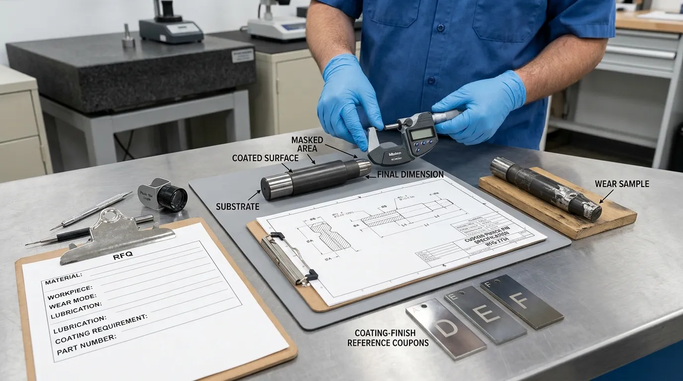
A supplier cannot select a coating responsibly from punch diameter and workpiece name alone. The RFQ should combine punch data, failure evidence, production conditions, and inspection requirements.
SunshinePro states that it produces custom non-standard components from drawings or samples. Its stamping punch page and punch pin pages provide relevant material and manufacturing context for a custom inquiry.
Application and Punch Data to Provide
Include:
- Punch drawing and revision
- Critical dimensions and tolerances
- Punch geometry and head configuration
- Substrate grade
- Final hardness or heat-treatment condition
- Existing coating or surface treatment
- Workpiece grade
- Workpiece surface coating
- Sheet thickness
- Punching, piercing, or forming operation
- Punch-to-die clearance
- Alignment status
- Lubrication
- Press speed
- Current failure mode
- Current production interval before failure
- Photographs of worn punches
- Failed punch samples where practical
- Target output
- Acceptance criteria
Describe the wear rather than writing only “short tool life.” State whether the problem is pickup, edge rounding, flaking, chipping, deformation, burr growth, part scratching, or another measurable condition.
Coating and Inspection Data to Request
Ask the supplier to identify:
- Generic coating family
- Proprietary coating-system name, if applicable
- Deposition process
- Nominal coating thickness
- Process-temperature compatibility
- Surface-preparation method
- Adhesion layer or multilayer architecture where relevant
- Masked surfaces
- Final roughness requirement
- Final-dimensional responsibility
- Inspection method
- Coating certificate or process record
- Regrinding instructions
- Stripping and recoating limitations
Not every order requires laboratory adhesion testing, but the buyer should know what evidence is available when the risk justifies it.
The punch manufacturer and coating provider should review the application together where possible. The manufacturer understands geometry, substrate, heat treatment, and final dimensions, while the coating provider understands deposition compatibility and coating-system limitations.
Validate the Recommendation in a Controlled Production Trial
Supplier data and laboratory tests can narrow the shortlist, but they cannot guarantee stamping performance. Validate promising candidates under production-representative conditions.
A useful trial should compare only a small number of defensible options. Testing too many coatings while changing other variables makes the result difficult to interpret.
Use the Same Conditions and Define Failure Before the Trial
Where practical, hold these variables constant:
- Punch geometry
- Punch substrate
- Heat treatment
- Edge preparation
- Die clearance
- Alignment
- Workpiece batch
- Lubricant
- Press settings
- Inspection method
Define failure before production begins. Possible endpoints include:
- Maximum dimensional wear
- Burr limit
- Material-pickup limit
- Surface-finish defect
- Coating delamination
- Excessive stripping force
- Tool chipping or fracture
Inspect the punch at planned intervals rather than only after complete failure. Wear progression can reveal whether a coating delays damage, changes the failure mechanism, or merely hides the early symptoms.
Compare Cost per Acceptable Part, Not Coating Price Alone
The least expensive coating is not always the lowest-cost option, and the longest-lasting coating is not automatically the most economical.
Include:
- Punch manufacturing cost
- Coating cost
- Regrinding cost
- Stripping and recoating cost
- Press downtime
- Cleaning and pickup removal
- Scrap
- Rework
- Acceptable-part output
A practical calculation is:
Total tooling and interruption cost ÷ acceptable parts produced
This avoids unsupported tool-life multipliers and keeps the decision tied to real production performance.
Use a Five-Step Coating Selection Sequence
A reliable punch-coating decision follows this order:
- Classify the failure. Separate adhesive wear, abrasion, delamination, chipping, and deformation.
- Correct non-coating causes. Review clearance, alignment, geometry, substrate, heat treatment, finish, and lubrication.
- Define the required properties. Prioritize adhesion, wear resistance, friction behavior, material affinity, toughness, or thermal stability according to the diagnosed condition.
- Confirm system compatibility. Check the coating family, substrate, deposition process, thickness, masking, finish, and final dimensions.
- Validate in production. Compare shortlisted systems under controlled conditions and measure cost per acceptable part.
SunshinePro supplies custom punch components based on drawings or samples and lists several punch materials and coating options on its product pages. To request a meaningful review, send the punch drawing, substrate, workpiece details, wear evidence, lubrication, and production conditions through the SunshinePro contact page. The objective should be a technically justified shortlist and trial plan—not a universal coating recommendation.
Share:


Written By Tonmoy
NEWS
GET SERVICE
With quality parts to meet every budget and friendly staff trained to make your visit informative and hassle free.
