



Mold Positioning Pin Material and Hardness Selection
Mold positioning pin material and hardness should be selected as a complete specification, not as a steel name followed by the highest available HRC value. The correct choice depends on contact frequency, side loading, impact risk, corrosion, lubrication, pin diameter, surface finish, and the material of the mating bushing.
Hardness improves resistance to indentation and wear, but excessive hardness or an unsuitable heat-treatment condition can reduce toughness and increase the risk of chipping or cracking. For wider context on alignment, fit, lubrication, and system wear, see mold pins and bushings (inferred). This guide focuses specifically on selecting and purchasing the pin’s material and hardness condition.
First Confirm the Pin’s Positioning Role
Manufacturers do not always use positioning pin terminology consistently. A positioning pin may also be described as a locating pin or centring pin, while some suppliers use guide pin or leader pin for a related component.
| Component term | Typical role | Material-selection implication |
|---|---|---|
| Positioning or locating pin | Establishes repeatable final location between mold components | Accuracy, contact wear, impact, and mating-bushing properties are critical |
| Guide pin or leader pin | Guides mold movement over a longer engagement distance | Straightness, sliding wear, lubrication, and bushing engagement become more prominent |
| General dowel pin | Establishes fixed component location in an assembly | May not experience the same repeated sliding or impact conditions |
| Ejector, core, or punch pin | Performs ejection, forming, cutting, or cavity-related work | Requires a different material-selection process |
A component can perform both guiding and final positioning functions, but the designer should confirm its actual loading before specifying the steel. A long guide pin exposed to sliding friction may need different properties from a short locating pin that receives repeated impact during mold closure.
For a broader explanation of guiding components, use the dedicated guide to mold guide pins. The material decisions below assume a pin used for repeatable mold positioning through engagement with a matching hole, insert, or bushing.
Start With the Operating Conditions, Not the Steel Grade
Before comparing materials, define how the pin will operate. A supplier cannot reliably select a material from diameter and length alone.
Review these conditions first:
- Contact frequency and production demand: Repeated engagement increases accumulated wear, even when each individual cycle produces only moderate contact stress.
- Impact and side loading: Misalignment, heavy mold sections, or abrupt engagement may require more core toughness than a lightly loaded precision locator.
- Pin diameter and section size: A steel that hardens effectively in a small pin may not produce the same through-section properties in a larger component.
- Required repeatability: Higher positioning accuracy increases the importance of dimensional stability, roundness, finish, and controlled wear.
- Mating-bushing design: The pin and bushing should be selected as a material pair rather than as isolated parts.
- Lubrication: Limited lubrication increases friction and the risk of adhesive wear, galling, or seizure.
- Contamination: Dust, metal particles, and molding residue can create abrasive wear.
- Corrosive exposure: Humidity, condensation, washdown, or chemical exposure may justify hardened stainless steel or a qualified protective treatment.
- Temperature: Elevated operating temperatures can affect hardness retention, lubricant performance, and coating suitability.
- Standard or custom sourcing: A catalog component may be adequate for common conditions, while unusual loading, size, or documentation requirements may require a drawing-defined part.
Material selection cannot correct poor alignment, unsuitable clearance, or an unstable layout. Those issues should be resolved separately before increasing pin hardness.
Compare the Main Material Strategies
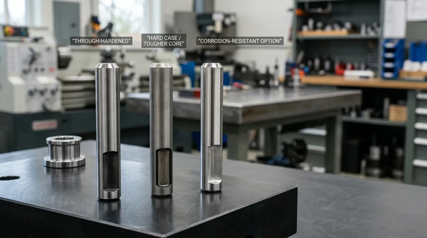
The useful comparison is not simply “steel versus stainless steel.” Buyers should compare material families together with their final heat-treatment condition.
| Material strategy | Main advantage | Main limitation | Typical selection logic |
| Through-hardened bearing steel | High hardness through much of the section and strong wear potential | May be less forgiving under impact or severe misalignment; corrosion protection may be needed | Repeated, controlled contact with good alignment and lubrication |
| Case-hardening alloy steel | Hard wear-resistant surface with a tougher supporting core | Case depth, distortion, and final grinding must be controlled | Repeated contact combined with shock, side loading, or impact risk |
| Hardened tool steel | Good wear resistance and potential dimensional stability when correctly processed | Performance varies significantly by grade and heat treatment | Custom geometry or demanding wear conditions requiring a defined tool-steel solution |
| Hardened stainless steel | Better corrosion resistance than conventional hardened carbon or alloy steels | Achievable hardness, galling behavior, toughness, and cost must be assessed | Humid, washed, condensed, or corrosion-prone environments |
Through-Hardening Bearing Steels
Through-hardening bearing steels can provide high hardness, strength, and wear resistance across a meaningful portion of the pin section. Ovako describes 100Cr6 as a through-hardening bearing steel intended for applications requiring high hardness and high-cycle fatigue performance.
This strategy can suit a well-aligned positioning system with repeated contact and controlled lubrication. However, the grade name alone does not define the finished pin. The drawing still needs a final hardness range, heat-treatment condition, dimensional requirements, and inspection method.
Regional designations such as SUJ2, GCr15, 100Cr6, and AISI 52100 may be treated as related bearing-steel families in commercial discussions, but they should not be substituted automatically. The governing material standard, chemistry, cleanliness requirements, and approved heat-treatment condition should be confirmed.
Case-Hardening Alloy Steels
Case-hardening steels are selected when the designer wants a hard contact surface supported by a tougher core. During carburizing, carbon is introduced into the surface before hardening, creating a wear-resistant case while retaining a different core condition.
Bodycote’s technical description of case hardening and carburizing explains how this approach can combine surface hardness with core toughness. That balance is useful when a positioning pin experiences repeated engagement, impact, or side loading.
A case-hardened specification should not stop at surface HRC. It may also need:
- Core-hardness requirements
- Effective case depth
- Test locations
- Post-treatment grinding allowance
- Straightness and diameter after final finishing
A very hard but shallow case may wear through prematurely. A deep case may be unnecessary or may complicate processing. The required depth should therefore be based on load, expected wear, pin geometry, and the chosen steel.
Hardened Tool Steels and Stainless Options
Hardened tool steels can be appropriate where wear resistance and dimensional control are important, but their performance depends heavily on the exact grade, hardness, tempering condition, and section size. “Tool steel” is not a complete purchase specification.
Hardened stainless steel is more relevant when corrosion exposure could damage a conventional hardened steel pin. A stainless option should still be evaluated for:
- Achievable hardness
- Core strength
- Galling tendency
- Surface finish
- Mating-bushing material
- Environmental severity
A stainless pin with inadequate hardness may resist rust but wear too quickly. A highly hardened stainless pin may still gall against an unsuitable mating material when lubrication is poor.
SunshinePro lists SUJ2, GCr15, SKD11, and alloy steel on its Locating Pin Guide Bushing page. Those are stated specifications for that bushing product and should not be interpreted as universal material options for every positioning pin.
Choose the Hardness Architecture, Not Just the Highest HRC
Two pins with the same measured surface hardness can behave differently because their hardness profiles and core conditions are different.
A through-hardened pin aims to develop hardness across the section, subject to the steel’s hardenability and the pin diameter. A case-hardened pin concentrates high hardness near the surface while maintaining a different core condition. Nitriding creates a hard surface layer through nitrogen diffusion and is sometimes chosen where wear, scuffing, galling resistance, or lower process distortion is important.
Bodycote notes that gas nitriding can improve resistance to wear, scuffing, galling, and seizure. Its suitability still depends on the base steel and the required layer characteristics.
| Selection factor | Through hardening | Case hardening | Nitriding |
| Hardness distribution | Extends through much of the section | Hard surface over a different core | Hardened diffusion layer near the surface |
| Tough-core potential | Depends on grade and final hardness | Central design advantage | Depends primarily on the pretreated base material |
| Case-depth requirement | Usually not applicable in the same way | Often essential | May be required when layer depth affects performance |
| Distortion control | Depends on grade, quenching, and geometry | Requires allowance for carburizing and quenching | Often selected where lower distortion is valuable |
| Best use | Controlled high-wear contact | Wear combined with shock or impact | Surface-wear or galling control on a suitable base steel |
No process is universally superior. Geometry, loading, distortion tolerance, final grinding, mating material, and supplier capability all affect the decision.
Surface Hardness, Core Hardness, and Effective Case Depth
A complete specification may need three separate properties:
- Surface hardness: The hardness at or near the working surface. It strongly influences resistance to indentation and contact wear.
- Core hardness: The hardness beneath the treated layer. It affects support, strength, and toughness.
- Effective case depth: The depth at which the material still meets a defined hardness criterion.
These values answer different questions. Surface hardness indicates how the contact area resists wear. Core hardness indicates whether the pin can support the surface under load. Effective case depth indicates how much usable hardened material exists before wear reaches a softer region.
For a through-hardened pin, a surface measurement may still be insufficient if section hardness is important. For a carburized pin, surface HRC without case-depth evidence does not fully describe the treated condition.
Specify Hardness So a Supplier Can Verify It
A requirement such as “hardened to HRC 60” leaves several questions unanswered:
- Is 60 a target, minimum, or nominal value?
- What range is acceptable?
- Where should the test be taken?
- Does it apply to the surface, core, or both?
- Which test method should be used?
- Is case depth required?
- Is the result measured directly or converted from another scale?
A stronger drawing or RFQ requirement should identify:
- Material grade and governing standard
- Heat-treatment route
- Acceptable hardness range
- Hardness scale
- Test location
- Surface or core applicability
- Effective case depth where needed
- Required inspection or test report
For hardened steels, Rockwell C is commonly used. ISO 6508-1:2023 defines the Rockwell hardness-test method, while ISO 6508-2:2023 addresses verification and calibration of Rockwell testing equipment and indenters.
Vickers testing may be more useful for localized measurements, thin treated zones, or a hardness profile across a section. The relevant method is defined in ISO 6507-1:2023.
Hardness conversions should be handled cautiously. ISO 18265 provides conversion principles, but a converted value is not automatically equivalent to a direct measurement under the required method. Material type, treatment condition, and measurement range can affect the relationship.
An incomplete requirement might state:
Hardened alloy steel, HRC 60.
A more usable requirement would define the material standard, treatment, acceptable HRC range, measurement location, core condition, case depth if applicable, and reporting expectations. The exact values must come from the application rather than a generic template.
Match the Pin and Bushing as a Wear System
The positioning pin and its mating bushing form one contact system. Selecting each component independently can create avoidable wear or seizure.
A common design approach is to make the replaceable bushing the preferred wear component. That may involve selecting a pin that is harder than the bushing, but there is no universal hardness difference that suits every material pair and load condition.
Check the following together:
- Pin material and hardness
- Bushing material and hardness
- Surface finish on both components
- Engagement length
- Clearance and alignment
- Lubrication method
- Contamination exposure
- Corrosion risk
- Coating or treatment thickness
- Replacement strategy
Two hard surfaces can still gall if their material pairing, finish, or lubrication is unsuitable. A rough or misaligned bushing can also damage a correctly hardened pin. Coatings and diffusion treatments may alter final dimensions, so diameter and fit should be verified after all relevant processing is complete.
SunshinePro’s locating-pin guide-bushing page states HRC 58–62, a precision-ground finish, and standard or custom sizes for that specific product. Those details may help when evaluating a matching bushing, but the final pin-and-bushing combination still needs project-specific review.
Select by Application Risk
The table below provides selection directions rather than fixed material prescriptions.
| Operating condition | Starting material or treatment direction | Main checks |
| High-cycle contact with good alignment and lubrication | Through-hardened bearing steel or another high-hardness steel strategy | Section hardness, finish, bushing pairing, dimensional stability |
| Repeated impact or side loading | Case-hardening alloy steel with a hard case and controlled core | Core toughness, case depth, distortion, final grinding |
| Humid, condensed, or frequently cleaned environment | Hardened stainless steel or qualified corrosion-protection strategy | Achievable hardness, galling, chemical exposure, mating material |
| Limited lubrication | Suitable material pair, fine finish, and possible nitriding or other qualified surface treatment | Galling, seizure, treatment compatibility, final dimensions |
| Abrasive contamination | High surface wear resistance plus contamination control | Finish, sealing or cleaning strategy, case depth, bushing replacement |
| Large pin diameter | Steel with adequate hardenability or a case-hardening strategy | Through-section properties, core condition, heat-treatment uniformity |
| Tight dimensional control after heat treatment | Material and process selected for stable final grinding | Grinding allowance, straightness, roundness, inspection after treatment |
These directions should be confirmed against the actual pin geometry, load, mold construction, and supplier process. Material selection should reduce risk, not replace engineering validation.
Put the Complete Requirement on the Drawing or RFQ
A useful RFQ gives the supplier enough information to evaluate material availability, heat treatment, inspection, and manufacturability.
Include:
- Part function and drawing revision
- Pin diameter, length, geometry, and engagement area
- Exact material grade and governing standard
- Approved or prohibited substitute grades
- Heat-treatment route and final condition
- Surface-hardness range and scale
- Core-hardness requirement where necessary
- Effective case depth where necessary
- Hardness-test location and method
- Surface finish
- Diameter tolerance
- Straightness and roundness requirements
- Coating or surface treatment
- Dimensional allowance for coating thickness
- Mating-bushing material and hardness
- Required material certificate
- Heat-treatment record or certificate
- Hardness-test report
- Case-depth report where applicable
- Final dimensional inspection report
- Traceability and sampling expectations
Standard catalog components may already have fixed material and hardness conditions. A custom pin needs clearer drawing control because the buyer is defining the final properties. The guide to mold standard parts provides additional context on deciding between standard and customized mold components.
Supplier Red Flags
Review the quotation carefully when it contains any of these problems:
- “Hardened steel” with no grade or standard
- One hardness number with no scale or range
- No heat-treatment condition
- Surface hardness presented as proof of core hardness
- No case-depth requirement for a case-hardened design
- Informal grade substitution without approval
- Converted hardness values used as the only evidence
- No defined test location
- Coating specified without final-size verification
- Service-life claims without load, fit, lubrication, and environmental conditions
A lower-cost quotation is not comparable if it omits material traceability, treatment details, or inspection requirements included in another supplier’s offer.
SunshinePro Context for Standard and Custom Requirements
SunshinePro’s website lists guide pins and bushings, guide posts and bushings, standard mold components, and custom mold accessories. It also states that non-standard accessories can be produced from customer drawings or samples and that material-selection support is available.
Its Locating Pin Guide Bushing page lists SUJ2, GCr15, SKD11, alloy steel, HRC 58–62, a precision-ground finish, and standard or custom sizes. These are product-specific bushing details. They should not be applied automatically to every positioning-pin design or treated as proof that every material, treatment, or inspection method is available for every custom part.
A technical enquiry should therefore include the complete drawing and specification rather than only a requested diameter and hardness.
Material and Hardness Selection Checklist
Before approving a mold positioning pin specification, confirm that you have:
- Identified whether the component performs final positioning, general guidance, or both.
- Defined contact frequency, impact, side loading, lubrication, contamination, and corrosion exposure.
- Reviewed the mating-bushing material, hardness, finish, and replacement strategy.
- Selected a material family based on the operating risks.
- Chosen through hardening, case hardening, or another qualified treatment route.
- Defined surface hardness and core requirements separately where needed.
- Added effective case depth for a case-hardened or nitrided design when relevant.
- Specified the hardness scale, range, test method, and test location.
- Controlled final finish, diameter, straightness, roundness, and coating allowance.
- Requested the material, heat-treatment, hardness, case-depth, and dimensional records appropriate to the project.
Once these requirements are defined, submit the drawing and technical conditions through SunshinePro’s contact page for feasibility review or a quotation. The enquiry should make clear which requirements are mandatory and where qualified alternatives may be considered.
Share:


Written By Tonmoy
NEWS
GET SERVICE
With quality parts to meet every budget and friendly staff trained to make your visit informative and hassle free.
