



Straight vs Tapered Mold Positioning Pins: Which Fits the Mold?
Straight and tapered mold positioning pins solve the same broad problem—bringing mating mold plates into a controlled final position—but they do it differently.
A straight positioning set works best when the mold’s main guide system already controls the approach accurately and the designer needs close, repeatable pre-positioning. A tapered positioning set adds progressive lead-in, allowing the mating components to capture limited offset as the mold closes.
Neither design is automatically more accurate or durable. The correct choice depends on engagement sequence, approach alignment, pin-to-bushing fit, parting-line conditions, taper seating, sensitive mold features, and maintenance access. These positioning components also operate inside a wider system of mold pins and bushings (inferred), rather than replacing the mold’s primary guidance by themselves.
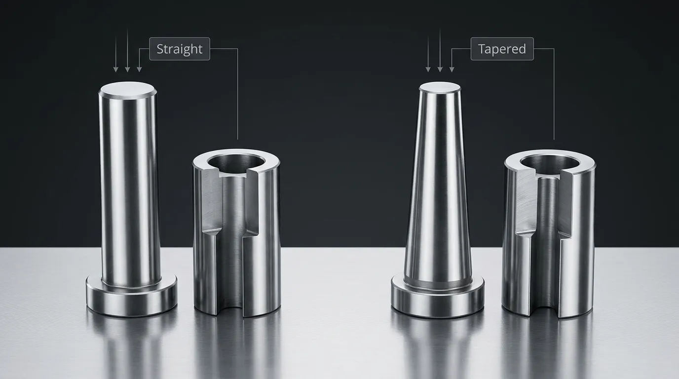
Straight and Tapered Positioning Sets at a Glance
The comparison should cover the complete pin-and-bushing pair, not only the visible pin shape.
| Comparison factor | Straight positioning set | Tapered positioning set |
|---|---|---|
| Locating geometry | Parallel or cylindrical locating surface | Conical or tapered locating surface |
| Entry behavior | Enters at nearly constant clearance | Clearance reduces progressively during entry |
| Approach requirement | Usually needs well-controlled prior alignment | Can capture a limited amount of approach offset |
| Final positioning | Determined mainly by pin-to-bushing fit and alignment | Determined by taper geometry, seating position, and mating accuracy |
| Closure condition | Some designs require parting-line clearance at full closure | Some designs can be configured for full taper contact at closure |
| Main advantage | Controlled, repeatable pre-positioning | Progressive lead-in and geometric capture |
| Main limitation | Can bind if close-fitting parts enter off-axis | Can wedge or develop uneven contact if seating is incorrect |
| Best-fit condition | Stable guide system and predictable mold approach | A need for controlled correction during final engagement |
| Retrofit difficulty | Replacement must preserve fit and axis location | Conversion requires review of taper, seating, mounting, and mating geometry |
A straight system is not merely a tapered system without an angle. The geometry changes how the components enter, where contact develops, and how positional error is transferred into the mold plates.
How Each Geometry Engages as the Mold Closes
The mold’s leader pins and guide bushings normally control the initial movement of the two mold halves. Positioning pins act later in the closing sequence, refining plate location before sensitive features make full contact.
A typical sequence is:
- The leader pins enter their guide bushings and establish the general closing path.
- The positioning pin begins entering its mating bushing.
- The positioning set reduces the remaining lateral movement between the plates.
- Core pins, inserts, shutoffs, or other close-clearance features reach their final engagement.
- The mold reaches its designed closed condition.
This sequence matters because positioning components should normally control plate location before delicate features are forced to absorb misalignment. MISUMI’s mold-component documentation, for example, describes positioning sets intended to engage before core pins and also notes the need for an appropriate precision leader-pin system. Exact timing still depends on the specific mold design and selected component set.
The primary guidance function belongs to mold guide pins. Positioning pins supplement that guidance near final closure; they should not be expected to correct a damaged guide system, severe platen movement, or major mold-base error.
How a Straight Positioning Set Engages
A straight positioning pin enters a cylindrical mating bore. Because the locating surfaces remain parallel, the available entry clearance does not progressively increase toward the tip in the same way as a full tapered locating interface.
This makes prior alignment important. When the leader-pin system has already brought the mold plates close to their intended axes, a straight positioning set can provide controlled and repeatable pre-positioning. The final movement between the pin and bushing depends heavily on their specified fit.
The same close fit that improves positional control can also increase sensitivity to:
- Off-axis entry
- Contamination in the bushing
- Damaged or raised edges
- Incorrect concentricity
- Thermal or structural movement
- Redundant locating points that overconstrain the plates
Some catalog straight positioning systems require a small parting-line clearance when the mold is fully closed. That requirement prevents the positioning components from unintentionally carrying closure load or interfering with full plate contact. It is product-specific and must be taken from the selected supplier’s drawing rather than treated as a universal value.
How a Tapered Positioning Set Engages
A tapered pin enters a matching tapered bushing or seat. At the beginning of engagement, the smaller leading section provides more room for entry. As the mold continues to close, the available radial clearance decreases and the taper progressively guides the mating components toward a common axis.
This progressive capture is the main reason to consider a tapered system. It can tolerate a limited amount of initial offset that might cause edge contact in a close straight interface.
Final performance, however, depends on more than the presence of a taper. The designer must control:
- Taper angle or taper ratio
- Axial seating position
- Concentricity between locating and mounting features
- Engagement length
- Contact distribution
- Parting-line condition
- Retention and removal method
Some supplier systems can be arranged to reach full taper contact or zero clearance at mold closure. That behavior applies only to the documented design. It should not be generalized to every tapered positioning pin.
If the taper seats too deeply, uses incompatible mating angles, or enters under excessive offset, it may create wedging, uneven contact, difficult release, or unwanted load on the mold plates.
The Selection Criteria That Actually Decide the Better Fit
The pin shape should not be selected in isolation. The mold’s approach behavior and final positioning requirement are more important than a general preference for straight or tapered components.
| Selection criterion | Straight is usually favored when… | Tapered is usually favored when… |
| Initial approach alignment | The leader-pin system already controls the axes closely | Limited approach offset must be captured progressively |
| Final positional requirement | A specified cylindrical fit can provide the required control | Final location is established through controlled taper seating |
| Sensitive mold features | Pre-positioning is needed before cores or inserts engage | Gradual correction is needed before shutoffs or close features contact |
| Entry sensitivity | Off-axis entry is minimal and predictable | Some lead-in is needed to reduce abrupt edge contact |
| Closure condition | Required operating or parting-line clearance can be maintained | Full seating behavior can be defined and controlled |
| Risk to manage | Binding and scoring | Wedging and uneven taper contact |
| Mounting control | Pin and bushing axes can be held accurately | Taper axis and axial seating can both be held accurately |
| Replacement strategy | Direct cylindrical replacement is practical | Matched taper geometry and seating can be reproduced |
| Component availability | A suitable standard straight set exists | A suitable standard taper set exists or a custom design is justified |
The decision also depends on whether the required component exists as a standard catalog item. Where diameter, taper, mounting, retention, or engagement conditions fall outside standard ranges, a drawing-based part may be necessary. SunshinePro states that it supplies both standard components and non-standard mold parts processed from customer drawings. Its broader guidance on mold standard parts can help separate catalog selection from customization.
When a Straight Positioning Set Is the Better Choice
A straight positioning system is generally the stronger candidate when the mold’s initial guidance is already stable.
Typical conditions include:
- The leader pins and guide bushings keep plate approach error low.
- The positioning set needs to establish a close, repeatable location before core pins engage.
- The designer can specify and inspect the cylindrical pin-to-bushing fit.
- Parting-line clearance requirements are known.
- Mounting bores and locating axes can be held concentric.
- Contamination and off-axis impact can be controlled.
- Replacement components can reproduce the original fit.
Consider a mold containing several delicate core pins that enter close-clearance holes near the end of closure. If the main guide system already brings the two mold halves into reliable alignment, a straight positioning set can refine their location before those core pins enter.
The design becomes less suitable when significant lateral error remains at the start of positioning engagement. A close straight fit should not be used as a substitute for correcting damaged leader pins, worn guide bushings, or mislocated mounting bores.
When a Tapered Positioning Set Is the Better Choice
A tapered positioning system is generally more appropriate when the mold needs a controlled lead-in before reaching its final position.
Typical conditions include:
- Limited approach variation remains after the main guide system engages.
- The mold needs progressive rather than abrupt correction.
- The taper can engage before sensitive shutoffs, inserts, or cores reach contact.
- Taper angle, axial seating, and contact position can be defined accurately.
- The design can prevent excessive seating force.
- Removal access is available if the taper becomes tightly seated.
- The selected supplier can reproduce the complete mating geometry.
A tapered system may be useful when two plates approach with a small lateral offset that is acceptable at the start of engagement but must be reduced before a close shutoff meets its mating surface. The taper introduces correction gradually as engagement increases.
That does not mean a tapered pin can repair a poorly guided mold. Its capture range is limited by the actual geometry. Forcing a taper to correct excessive offset can concentrate load on one side of the pin and bushing, damage the contact surfaces, or shift stress into the surrounding mold plate.
Risks, Failure Modes, and Retrofit Mistakes
Straight and tapered systems fail in different ways, although both are sensitive to poor mounting, contamination, wear, and incorrect engagement order.
| Risk | Likely cause | Possible result | Design response |
| Straight-set binding | Tight fit combined with off-axis entry | Jamming, scoring, plate damage | Improve prior guidance and verify operating clearance |
| Edge loading | Misaligned pin contacts the bushing edge | Local wear, chipping, deformation | Review engagement timing and axis location |
| Taper wedging | Excessive axial seating or unsuitable taper geometry | Difficult opening, unwanted preload | Define the axial stop and mating taper accurately |
| Uneven taper contact | Angle, concentricity, or mounting error | Localized wear and poor final location | Inspect taper geometry and mounting datums |
| Galling or scoring | Poor finish, material pairing, lubrication, or contamination | Rough movement and accelerated wear | Specify contact surfaces and maintenance conditions |
| Wear-induced clearance | Repeated contact and insufficient support | Increased positional movement | Define inspection and replacement criteria |
| Premature feature contact | Positioning set engages too late | Damage to cores, inserts, or shutoffs | Correct the engagement sequence |
| Difficult component removal | No extraction feature or rear access | Longer maintenance and plate damage risk | Include dismounting taps or planned service access |
One of the most common design mistakes is treating straight and tapered positioning sets as interchangeable.
Changing a straight pin to a tapered pin affects the mating bushing, installation depth, axial seating, contact pattern, parting-line condition, and removal method. The surrounding mold plate may also need different machining. A retrofit should therefore be reviewed as a system change, not a simple pin substitution.
The reverse is also true. Replacing a tapered system with a straight fit may remove the original lead-in and make the mold more sensitive to approach error.
What the Drawing and RFQ Must Specify
A supplier cannot evaluate a positioning system accurately from pin diameter alone. The drawing or request for quotation should define the complete mating arrangement.
Include:
- Straight or tapered positioning geometry
- Pin and bushing dimensions
- Engagement length
- Taper angle or ratio, where applicable
- Intended fit or final seating condition
- Required parting-line clearance
- Pin and bushing mounting sides
- Retention method
- Axial seating or stop location
- Dismounting tap or extraction access
- Material requirements
- Heat-treatment and hardness requirements
- Surface-finish requirements
- Critical concentricity and dimensional tolerances
- Quantity
- Matched-set or interchangeable-replacement requirement
- Inspection dimensions
- Inspection-report requirements
- Relevant operating temperature, contamination, loading, or maintenance conditions
The pin and bushing should be treated as a mating system. Ask whether replacement components are individually interchangeable or whether the supplier expects them to remain a matched pair.
Detailed tolerance selection belongs in the component drawing and supplier review. Generic fit assumptions are risky because a straight sliding fit, a close positioning fit, and a fully seated taper behave differently during mold closure.
SunshinePro states that it can process non-standard mold parts from customer drawings. The company also describes raw-material inspection, in-process monitoring, final testing, and inspection reporting on its quality page. Those statements support asking about drawing review and critical inspection dimensions, but the exact process, tolerance, material, and report for a specific positioning set still need written confirmation.
Final Selection Rule
Choose a straight positioning set when the mold already has controlled approach guidance and needs close, repeatable pre-positioning.
Choose a tapered positioning set when limited approach offset must be captured progressively and the taper’s seating condition can be controlled.
Review another alignment solution when the mold has severe lateral movement, damaged guide components, major platen problems, or loads beyond what a positioning set should correct.
The better design is the one that matches the complete closing sequence, not the pin shape that appears more precise in isolation.
Preparing a Positioning-Component Drawing for Supplier Review
Before requesting a quotation, prepare a drawing that shows both sides of the mating system and identifies the functional datums. Include the mold-closing direction, engagement position, final closure condition, and any sensitive features that must be protected before contact.
A useful supplier submission should contain:
- The pin and bushing drawings
- The relevant mold-plate mounting details
- Required fit, clearance, or taper seating
- Material, hardness, finish, and inspection requirements
- Expected replacement and interchangeability conditions
SunshinePro offers standard and tailored mold-component solutions and accepts drawing-based non-standard part inquiries. For a straight or tapered positioning system, use the contact page to submit the complete mating design and request confirmation of manufacturability, critical inspection points, and replacement strategy.
Share:


Written By Tonmoy
NEWS
GET SERVICE
With quality parts to meet every budget and friendly staff trained to make your visit informative and hassle free.
