



Dowel Pin Press Fit for Injection Molds: H7 Fit Selection Guide
A dowel pin press fit for injection molds cannot be selected from the H7 designation alone. H7 defines the permitted size range of the hole, not the complete fit. The pin must also have a specified tolerance class or confirmed upper and lower diameter limits.
The correct pairing depends on which mold component must retain the dowel, whether the mating component must be removed, the nominal diameter, plate material, engagement length, and hole quality. Broader alignment systems are covered in mold pins and bushings (inferred). This guide focuses only on stationary dowel pins fitted into mold plates and related tooling components.
A dowel pin should also not be confused with a guide pin. Dowel pins locate assembled components, while mold guide pins repeatedly enter guide bushings as the mold opens and closes.
What Does H7 Mean in a Dowel-Pin Fit?
The ISO system assigns separate tolerance zones to holes and shafts. In an H7 designation:
- H identifies the position of the hole tolerance zone relative to the nominal size.
- 7 identifies the tolerance grade.
- The actual tolerance width changes with the nominal diameter.
- A separate shaft or pin class is needed to define the complete fit.
ISO 286-1 establishes the terminology and code system for tolerances, deviations, and fits. ISO 286-2 provides the diameter-specific limit deviations for holes and shafts.
This means a drawing note that specifies only “Ø10 H7” controls the hole but does not fully specify the dowel-pin relationship. The designer must also state the pin class, reference an applicable pin standard, or provide the acceptable pin diameter limits.
Why the Hole and Pin Need Separate Tolerance Classes
A nominal 10 mm hole is not manufactured at exactly 10.000 mm every time. It is permitted to fall between defined lower and upper limits. The dowel pin also has its own permitted dimensional range.
The fit depends on four values:
- Smallest permissible hole.
- Largest permissible hole.
- Smallest permissible pin.
- Largest permissible pin.
Changing only the pin class can turn the same H7 hole into a clearance, transition, or interference relationship. Classes such as h6, m6, n6, and p6 position the pin tolerance zone differently relative to the nominal-size line. Their suitability cannot be judged from the letters alone; the applicable ISO limits must be checked for the selected diameter.
Clearance, Transition, and Interference Outcomes
| Fit behavior | Dimensional condition | Typical functional purpose |
|---|---|---|
| Clearance | The hole remains larger than the pin at all permitted limits | Easy assembly, removal, or movement |
| Transition | The tolerance ranges permit either slight clearance or slight interference | Accurate location with tightly controlled assembly behavior |
| Interference | The pin remains larger than the hole at all permitted limits | Positive retention in the selected component |
An H7/m6 pairing should not automatically be described as a guaranteed press fit. Depending on the applicable limits, it may produce a transition condition. A tighter pin zone may provide more consistent interference, but greater interference is not automatically better. It can increase insertion force, damage the hole, distort a thin plate, or complicate future removal.
Select the Fit According to the Mold Component’s Function
Fit selection should begin with the mold assembly, not with a tolerance chart.
Identify:
- the component in which the dowel must remain fixed;
- the component that must locate over the dowel;
- how often the assembly will be separated;
- whether the dowel must be replaceable;
- whether the plate can safely support an interference fit.
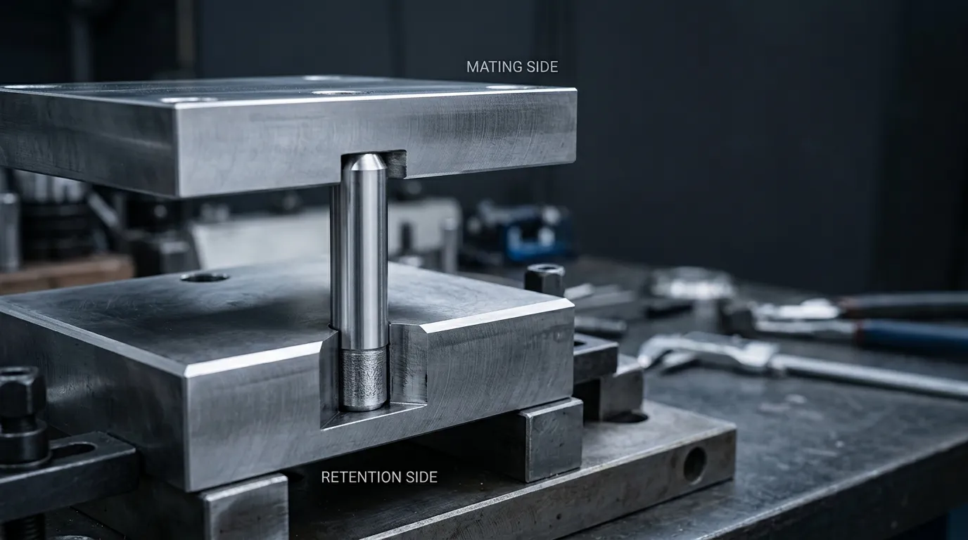
A common arrangement uses interference or a controlled transition condition on the retention side and a verified clearance condition in the mating component. This keeps the dowel attached to one plate while allowing the other component to assemble and separate without unnecessary binding.
The Retention Side: Where the Dowel Must Remain Fixed
The retention-side hole holds the dowel during mold assembly, handling, maintenance, and repeated separation of mating components.
Before selecting interference, check:
- plate material and hardness;
- plate thickness around the hole;
- distance from the hole to the nearest edge;
- dowel engagement length;
- access for future extraction;
- whether the plate is a permanent or replaceable component.
The tightest available fit should not be selected by default. The required retention must be balanced against local stress, installation force, and repairability.
For a blind installation, consider how the dowel will be removed before the hole is machined. A through hole, rear-side access, or an internally threaded pull dowel can prevent a simple locating component from becoming a maintenance problem.
The Mating Side: Location Without Unnecessary Binding
The mating component must locate accurately over the dowel, but it may also need to separate during mold servicing.
A clearance-oriented mating hole is generally more practical when the component is:
- removed frequently;
- assembled by hand;
- positioned by more than one dowel;
- sensitive to contamination or burrs;
- likely to experience temperature differences during assembly.
Press-fitting the same dowel tightly into two separate plates can make assembly sensitive to positional error. It may also prevent full seating, damage the hole edges, or make later separation difficult.
The correct arrangement depends on the application. A permanently assembled insert may justify a different relationship from a plate removed during every maintenance cycle.
Functional Fit-Selection Table
| Application condition | Desired result | Main verification |
| Dowel must remain in one robust plate | Controlled retention or guaranteed interference | Pin and hole limits, material, engagement, edge distance |
| Mating plate must be removed | Predictable assembly clearance | Largest pin versus smallest mating hole |
| Component requires highly accurate removable location | Closely controlled clearance or approved transition | Full tolerance stack and hole-position accuracy |
| Hole is worn or enlarged | Engineered oversize repair | Remaining plate material, new hole size, custom pin limits |
| Plate is thin or close to an edge | Limited local stress | Engineering review before increasing interference |
| Dowel is inaccessible from behind | Planned extraction feature | Pull-dowel style, threaded end, or alternate access |
Calculate the Worst-Case Clearance or Interference
Do not approve a dowel fit from nominal dimensions alone. Calculate both extreme manufactured conditions.
Use this process:
- Identify the nominal dowel diameter.
- Find the applicable diameter range in the current tolerance standard.
- Record the smallest and largest H7 hole dimensions.
- Record the smallest and largest pin dimensions.
- Calculate the loosest possible condition.
- Calculate the tightest possible condition.
- Confirm whether the complete range produces clearance, transition, or interference.
Use Both Tolerance Extremes
The basic calculations are:
Maximum clearance = largest hole − smallest pin
Minimum clearance = smallest hole − largest pin
A positive result represents clearance. A negative clearance result represents interference.
For example:
- If the minimum-clearance result is positive, clearance exists at every permitted combination.
- If one result is positive and the other is negative, the fit is transitional.
- If even the loosest combination produces a negative clearance value, interference is guaranteed within the specified limits.
Maximum interference can also be expressed as:
Maximum interference = largest pin − smallest hole
These calculations must use values from the same standard system and the correct nominal-diameter range. Do not mix a catalog pin tolerance, an ISO hole class, and an assumed nominal size without verifying that they are compatible.
Worked Example Method for a Mold Dowel
For a nominal 10 mm dowel, first retrieve the H7 hole limits and the selected pin-class limits from the current edition of ISO 286-2.
Then create a calculation table:
| Required value | Source |
| Smallest H7 hole | ISO 286-2 limit for the applicable diameter range |
| Largest H7 hole | ISO 286-2 limit for the applicable diameter range |
| Smallest pin | Selected pin-class or supplier drawing limit |
| Largest pin | Selected pin-class or supplier drawing limit |
| Maximum clearance | Largest hole minus smallest pin |
| Minimum clearance | Smallest hole minus largest pin |
The result establishes the dimensional relationship, but it does not by itself prove that the fit is safe for the mold plate. Plate material, local geometry, insertion method, and service conditions still need review.
Check the Mold Design Before Increasing Interference
Interference creates contact pressure between the pin and the hole wall. The same dimensional interference can behave differently in a thick hardened-steel plate and a thin, softer component near an edge.
Plate Material, Hardness, and Local Geometry
Review these factors before finalizing the fit:
- Plate material: Softer materials may deform more readily around the hole.
- Plate hardness: Affects how the hole responds during insertion and removal.
- Wall thickness: Thin sections may be less tolerant of high local pressure.
- Edge distance: A hole close to an edge has less surrounding material.
- Existing damage: Scoring, taper, cracking, or previous repair changes the joint condition.
- Hole depth: A deep blind hole may trap debris or air and complicate extraction.
Avoid assuming that a fit successfully used in one mold plate can be transferred unchanged to another material or geometry.
Engagement, Temperature, and Maintenance Frequency
Longer engagement increases the contact area between the pin and hole, but it can also increase installation and extraction difficulty. There is no universal engagement ratio suitable for every mold plate.
Temperature also matters when the pin and plate are measured or assembled under different conditions. Dimensional inspection and assembly should use a defined, controlled condition when the tolerance is tight enough for temperature variation to affect the result.
Maintenance frequency changes the preferred arrangement as well. A locating component that is separated regularly may benefit from a replaceable or extractable dowel design rather than a permanent blind press fit.
Machine and Inspect the Dowel Hole Correctly
A correct tolerance callout cannot compensate for a poorly produced hole. The final hole must have the required size, but it must also be positioned correctly and have acceptable form.
Drill, Ream, Deburr, and Clean
A practical hole-production sequence is:
- Establish the hole position from the correct mold datums.
- Secure and support the plate.
- Spot the hole where necessary to reduce drill walking.
- Drill below the final diameter.
- Ream to the specified final size using suitable tooling and process conditions.
- Deburr the entry and exit without creating a new sharp edge.
- Clean chips, abrasive particles, oil residue, and trapped debris.
- Inspect the hole before pressing the pin.
A reamer follows the existing hole. It can improve diameter and finish, but it cannot reliably correct severe drill wandering, poor straightness, chatter, or an incorrectly located axis. SPIROL’s hole-preparation guidance for press-fit pins likewise emphasizes rigid workholding and accurate drilling as prerequisites for producing a controlled hole.
Size Tolerance Does Not Control Hole Geometry
H7 controls the permitted hole size. It does not independently control:
| Dimensional control | Geometrical control |
| Minimum hole diameter | Hole position |
| Maximum hole diameter | Axis orientation |
| Size tolerance width | Straightness |
| Tolerance-zone location | Roundness or cylindricity |
A hole may measure within H7 limits and still cause binding if its axis is tilted, its form is tapered, or a two-hole pattern is incorrectly positioned.
ISO 1101 provides the symbol language and interpretation rules used for geometrical specifications. The mold drawing should apply only the geometric controls needed for the locating function rather than relying on the H7 size callout to control every feature.
Inspect the Pin and Hole Before Assembly
Before pressing the dowel:
- confirm the actual pin diameter or guaranteed supplier limits;
- verify the hole diameter with a suitable measurement method;
- check for taper, bell-mouth, burrs, and surface damage;
- confirm that the hole and pin are clean;
- verify that the hole position permits the mating component to assemble;
- inspect at a controlled temperature when the tolerance is sensitive to thermal variation.
A catalog description such as “precision ground” does not replace the dimensional limits required for the calculation.
Install, Remove, and Repair the Dowel Without Damaging the Mold
Correct installation keeps the pin aligned with the hole axis and prevents unnecessary damage to the plate.
Controlled Press Installation
Use the following sequence:
- Inspect the pin and hole.
- Confirm the intended insertion end and lead-in.
- Support the plate close to the hole.
- Align the pin with the hole axis.
- Apply controlled axial force with appropriate pressing equipment.
- Monitor the insertion for sudden resistance or misalignment.
- Stop and inspect rather than forcing an abnormal fit.
Uncontrolled hammering can tilt the pin, damage the entry edge, mark the ground surface, or enlarge the first part of the hole. A press does not correct an excessive tolerance mismatch; it only applies force more controllably.
Plan Extraction and Worn-Hole Repair
A dowel in a through hole can often be driven or pressed out from the rear. Blind holes need a planned removal method, such as:
- an internally threaded pull dowel;
- an accessible extraction feature;
- a removable locating bushing;
- a plate design that permits rear access.
After removal, measure the hole instead of installing a new pin automatically. A loose, tapered, scored, or enlarged hole may no longer provide the intended retention.
An oversize repair may be possible by reaming the damaged hole to a controlled new diameter and specifying a matching pin. The repair must leave enough surrounding plate material and preserve the required hole position. Update the drawing so future replacements are not ordered to the original size.
Specify the Dowel Fit on the Drawing and Supplier RFQ
A complete drawing should communicate the functional relationship, not just the nominal diameter.
Minimum Drawing Callouts
Include:
- nominal pin diameter;
- dowel length;
- H7 or other hole tolerance;
- pin tolerance class or explicit diameter limits;
- applicable pin standard;
- pin material and hardness requirement;
- surface-finish requirement where functional;
- retention-side component;
- required engagement length;
- mating-hole size and tolerance;
- relevant hole-position or orientation controls;
- end form or extraction feature;
- quantity and inspection-document requirements.
ISO 8734 covers parallel dowel pins made from hardened steel and martensitic stainless steel. ISO 2338 covers parallel pins made from unhardened steel and austenitic stainless steel. Referencing a product standard helps define the pin category, but the drawing must still establish the fit required by the mold assembly.
Questions to Confirm With the Dowel-Pin Supplier
Ask the supplier:
- What upper and lower pin diameters are guaranteed?
- Which tolerance standard and edition are being used?
- Does the quoted tolerance apply to the selected diameter and material?
- What material and hardness options are available?
- Can a custom or oversize repair diameter be produced?
- Which dimensional or material records can be supplied?
- Does the supplier need the plate material, engagement length, or required fit condition?
SunshinePro’s Dowel Pin product page lists straight, tapered, and custom configurations, along with alloy steel, stainless steel, and tool steel options. It also states that diameter, length, tolerance class, material grade, and surface finish can be customized, with CNC machining, grinding, and heat treatment listed as production processes. These are supplier-level options, not proof that one tolerance or material is correct for every mold.
A catalog component may be suitable when its actual limits match the calculation. Where a standard component does not meet the required diameter, material, removal feature, or repair size, review the choice between custom and mold standard parts.
Final Dowel-Fit Selection Checklist
Before releasing the drawing or repairing the mold:
- Identify the component that must retain the dowel.
- Define how the mating component will assemble and separate.
- Select the required functional behavior: clearance, transition, or interference.
- Retrieve the correct diameter-specific hole and pin limits.
- Calculate the tightest and loosest possible conditions.
- Check plate material, hardness, wall thickness, edge distance, and engagement.
- Confirm that the hole can be machined and geometrically controlled.
- Define the inspection method.
- Plan controlled installation.
- Provide a future removal method.
- Complete the drawing with both hole and pin requirements.
- Confirm the supplier’s actual dimensional limits before ordering.
For a custom dowel or repair size, submit the mold drawing, nominal diameter, required fit, plate material, engagement length, and inspection expectations through SunshinePro’s contact page. The final tolerance should be confirmed against the actual application rather than selected from the H7 designation alone.
Share:


Written By Tonmoy
NEWS
GET SERVICE
With quality parts to meet every budget and friendly staff trained to make your visit informative and hassle free.
