



Punch and Die Clearance Calculation by Material and Thickness
Punch and die clearance is normally calculated from sheet thickness and a material-dependent clearance ratio:
- Per-side clearance:
c = t × r - Total clearance:
C = 2c
Here, t is the sheet thickness and r is the clearance ratio expressed as a decimal. A 10% per-side ratio becomes 0.10 in the formula.
The calculation must also account for the operation. In piercing, the punch normally controls the finished hole size. In blanking, the die opening normally controls the finished blank size. This guide focuses only on that calculation and its practical validation. For broader information about die types, materials, tolerances, and sourcing, see the punching dies guide (inferred).
A calculated result is a starting value, not a universal production setting. Material grade, tensile strength, thickness variation, tooling wear, alignment, press deflection, and the required cut-edge condition can all justify adjustment.
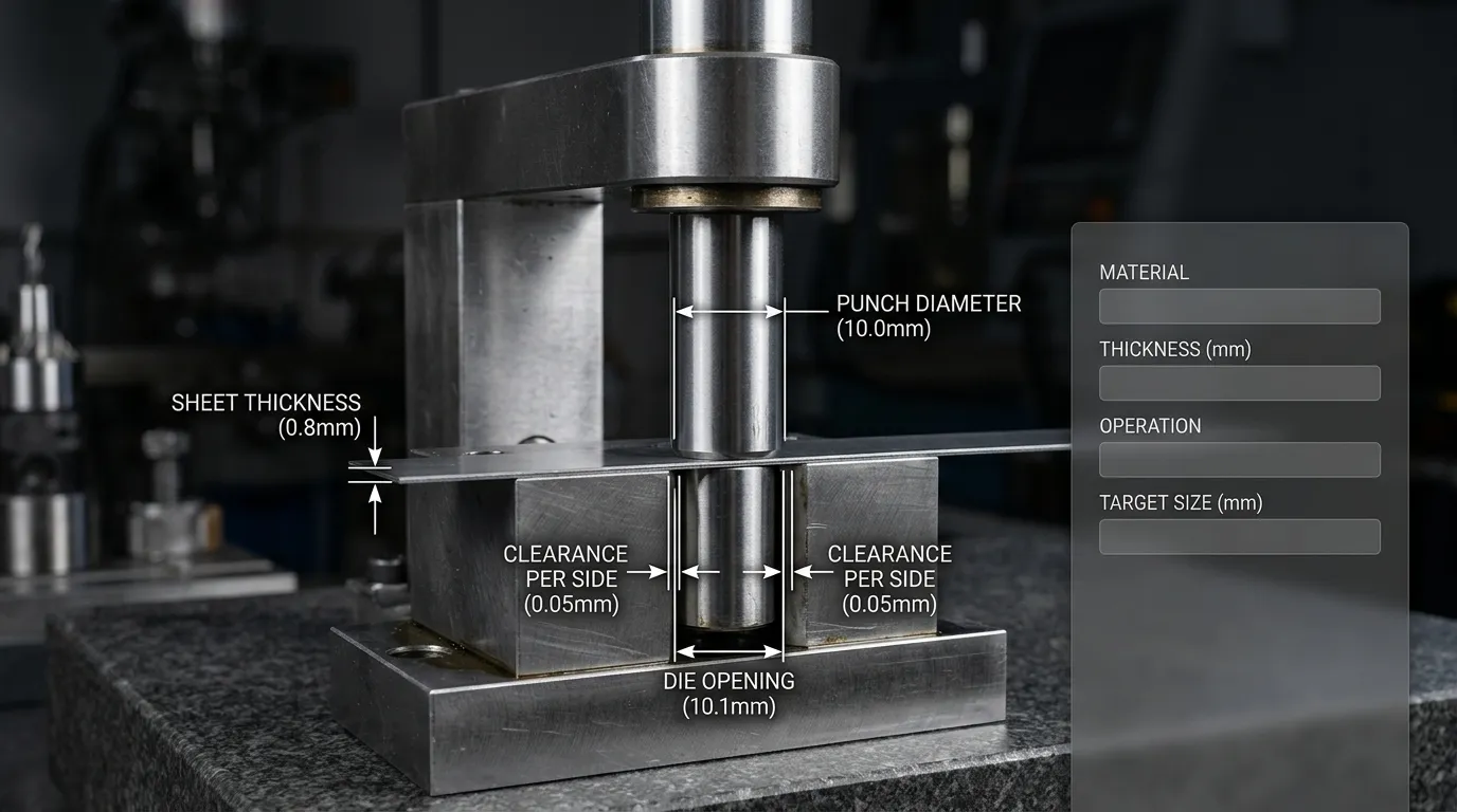
Punch and Die Clearance Calculator
Use the following inputs:
| Input | What to enter |
|---|---|
Sheet thickness, t | Actual or nominal thickness in mm or inches |
| Material | Aluminum, copper, brass, steel, stainless steel, or a documented grade |
Clearance ratio, r | A clearly labelled per-side percentage |
| Operation | Piercing or blanking |
| Target dimension | Finished hole size for piercing or finished blank size for blanking |
The calculator sequence is:
- Convert the selected percentage into a decimal.
- Multiply thickness by the ratio to obtain clearance per side.
- Multiply the per-side result by two to obtain total clearance.
- Apply total clearance according to whether the operation is piercing or blanking.
Per-side clearance:
c = t × rTotal clearance:
C = 2 × cPiercing die opening:
Ddie = Dpunch + CBlanking punch size:
Dpunch = Dblank − C
Run the entire calculation in one unit system. If thickness is entered in millimetres, all resulting punch and die dimensions will be in millimetres. Convert the final values to inches only when needed.
Enter Material, Thickness, Operation, and Target Size
Use the actual material thickness when it is available. Nominal gauge values can differ from the measured stock, and that difference transfers directly into the calculated clearance.
Material family provides an initial ratio, but it does not replace the exact grade. “Steel,” for example, can refer to materials with very different tensile strengths and cutting behavior. For high-strength steel, hardened stock, or an unlisted alloy, use grade-specific data or request an engineering review rather than selecting the nearest generic material.
Select the operation carefully:
- Piercing: the required feature is the hole left in the sheet.
- Blanking: the removed piece is the required finished part.
Entering the same target dimension for the wrong operation produces the wrong punch or die size.
Read the Result: Per-Side, Total, Punch, and Die Dimensions
A useful result should show more than one number. It should identify:
- the material category;
- the selected ratio;
- whether that ratio is per side or total;
- clearance per side;
- total clearance;
- the dimension controlled by the operation;
- calculated punch size;
- calculated die opening;
- metric and imperial equivalents;
- any limitation attached to the selected material.
Avoid rounding too early. Keep the full calculated value through the arithmetic, then round the final tooling dimension according to the drawing tolerance and practical manufacturing resolution.
How the Clearance Calculation Works
Punch-to-die clearance is the gap between the cutting edge of the punch and the corresponding cutting edge of the die. MISUMI defines its recommended percentages as clearance per side, meaning the percentage applies independently to each cutting edge.
The distinction matters because other references use “die clearance” to mean the full difference between punch and die dimensions. CONIC, for example, defines clearance as the difference between the punch dimension and die dimension, while Roper Whitney-style references may also describe a total die-clearance value. A percentage cannot be transferred safely from one formula to another until its convention is confirmed.
Per-Side Clearance Versus Total Clearance
Assume a round punch has a diameter of 10.00 mm and a die opening of 10.20 mm.
The dimensional difference is:
10.20 − 10.00 = 0.20 mm
That 0.20 mm is the total or diametral clearance. The clearance at each cutting edge is:
0.20 ÷ 2 = 0.10 mm per side
| Convention | Meaning | Value in this example |
| Per-side or radial clearance | Gap at one cutting edge | 0.10 mm |
| Total or diametral clearance | Full difference between punch and die sizes | 0.20 mm |
If a chart recommends 10% per side, calculate t × 0.10 and then double the result for the full punch-to-die dimensional difference.
If a chart recommends 20% total clearance, calculate t × 0.20 once. Do not double it again.
The Base Formulas
For a source that specifies a per-side ratio:
c = t × r
Where:
c= clearance per side;t= sheet thickness;r= per-side clearance ratio as a decimal.
Then:
C = 2c
Where:
C= total clearance between the punch and die dimensions.
For a 1.0 mm sheet with 8% clearance per side:
c = 1.0 × 0.08 = 0.08 mm
C = 2 × 0.08 = 0.16 mm
The percentage represents a proportion of thickness. A thicker sheet therefore produces a larger dimensional clearance even when the selected ratio remains unchanged.
Piercing and Blanking Use the Clearance Differently
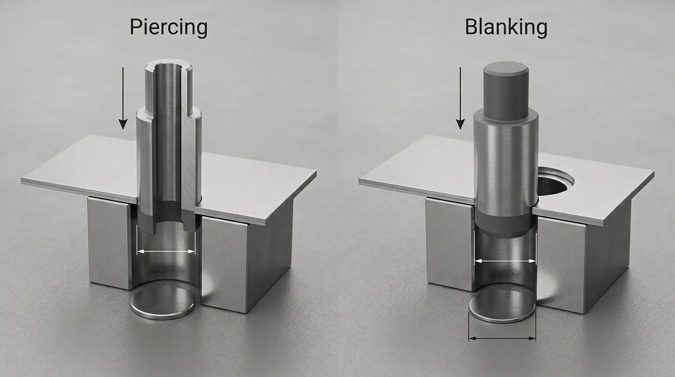
The same per-side clearance can be used in both operations, but it is applied to different tooling dimensions.
| Operation | Finished item | Dimension normally held to target | Mating dimension |
| Piercing | Hole in the sheet | Punch size | Die opening is larger |
| Blanking | Piece removed from the sheet | Die opening | Punch is smaller |
Mate’s tooling guide states that, during blanking, the die size is the blank size and the punch dimensions are calculated from the die dimensions.
Piercing Calculation
In piercing, the punch normally determines the finished hole dimension.
For a required hole diameter of Dh:
Dpunch = Dh
Ddie = Dh + C
If the target hole is 12.00 mm and total clearance is 0.24 mm:
- Punch size:
12.00 mm - Die opening:
12.24 mm
The removed slug is scrap. Its dimensions and edge appearance may still provide useful evidence when checking whether the clearance is working correctly.
Blanking Calculation
In blanking, the removed piece is the required part, so the die opening normally determines its outside dimension.
For a required blank dimension of Db:
Ddie = Db
Dpunch = Db − C
If the required blank is 30.00 mm and total clearance is 0.24 mm:
- Die opening:
30.00 mm - Punch size:
29.76 mm
Blanking may require additional adjustment when straight walls, reduced taper, or a particular burnish depth is critical. Mate recommends identifying critical blank dimensions and treating blanking tooling differently from ordinary piercing.
Starting Clearance by Material and Thickness
The following table uses the standard-grade, one-side values published in MISUMI’s clearance-selection reference. These percentages are starting references, not universal settings. The material-condition labels are the source’s categories and should be checked against the actual grade, tensile strength, alloy, or temper.
| Material category | Condition | Starting clearance per side |
| Aluminum alloy | Soft | 6% of thickness |
| Aluminum alloy | Medium | 8% of thickness |
| Aluminum alloy | Hard | 10% of thickness |
| Tough-pitch copper | Soft | 8% of thickness |
| Tough-pitch copper | Hard | 10% of thickness |
| Brass | Soft | 8% of thickness |
| Brass | Hard | 10% of thickness |
| Steel | Extra soft | 10% of thickness |
| Steel | Soft | 12% of thickness |
| Steel | Hard | 15% of thickness |
| Stainless steel | Soft | 12% of thickness |
| Stainless steel | Hard | 15% of thickness |
For example, medium aluminum at 1.5 mm thickness using an 8% per-side ratio gives:
c = 1.5 × 0.08 = 0.12 mm per side
C = 0.24 mm total clearance
How to Choose a Starting Ratio
Use this sequence:
- Identify the exact material grade, alloy, or temper.
- Confirm the measured or tolerance-controlled thickness.
- Choose a published material category that genuinely matches the stock.
- Confirm whether the source percentage is per side or total.
- Calculate the dimensional clearance.
- Check whether the press, tooling system, and required edge condition impose a different recommendation.
- Validate the result with a trial cut before final production.
Do not select the smallest available percentage merely to obtain a larger burnish zone. Tighter clearance increases sensitivity to alignment and can accelerate wear.
When Tensile Strength Should Override the Material Menu
For high-strength steels, a broad “steel” selection is not enough. The AHSS Application Guidelines state that clearance generally increases as tensile strength rises, while also warning that excessively wide clearance at the highest strengths can increase punch-edge bending stress and chipping risk. The recommended value is therefore a function of grade, thickness, tensile strength, and the required downstream edge performance.
The same guidance reports that historical mild-steel values often fall around 5–10% of thickness per side, while recommendations for stronger grades can be substantially higher. It also shows that one percentage does not produce the best result for every AHSS grade.
Use grade-specific data or a controlled punching trial when working with:
- AHSS or ultra-high-strength steel;
- martensitic grades;
- hardened sheet;
- material with uncertain tensile strength;
- stock intended for later edge stretching or forming;
- parts with strict fatigue or fracture requirements.
Why Published Clearance Charts Disagree
Two technically credible charts can show different values because they may use:
- per-side versus total-clearance conventions;
- different material conditions or tensile strengths;
- different press and tooling systems;
- precision-grade versus standard-grade targets;
- different requirements for burr, rollover, burnish, or tool life;
- proprietary tooling assumptions;
- different thickness ranges.
For example, UniPunch’s calculator publishes factors of 15% for aluminum, 20% for mild steel, and 25% for stainless steel as “die clearance required,” but the page does not explicitly label those factors as per-side values. They should not be inserted into a per-side formula without confirming the intended convention.
CONIC also publishes different ratios for mechanical machines and servo or hydraulic machines and advises users to consider tensile strength, thickness, machine limitations, and an actual punching trial.
Worked Calculation Examples
Piercing Example
Requirement: Pierce a 10.00 mm hole in 1.20 mm medium aluminum.
From the reference table:
- Material: medium aluminum
- Per-side ratio: 8%
- Thickness: 1.20 mm
Calculate clearance per side:
c = 1.20 × 0.08
c = 0.096 mm
Calculate total clearance:
C = 2 × 0.096
C = 0.192 mm
Apply the piercing dimensions:
- Punch size:
10.000 mm - Die opening:
10.000 + 0.192 = 10.192 mm
The calculated die opening may be stated as 10.19 mm if that rounding is compatible with the drawing, tooling process, and tolerance. Do not round the intermediate per-side value before calculating the total.
Blanking Example
Requirement: Produce a 25.00 mm blank from 1.50 mm soft brass.
From the reference table:
- Material: soft brass
- Per-side ratio: 8%
- Thickness: 1.50 mm
Calculate clearance per side:
c = 1.50 × 0.08
c = 0.120 mm
Calculate total clearance:
C = 2 × 0.120
C = 0.240 mm
Apply the blanking dimensions:
- Die opening:
25.000 mm - Punch size:
25.000 − 0.240 = 24.760 mm
These dimensions are calculation examples. Final tooling dimensions still depend on the actual material, blank tolerance, expected edge taper, tool condition, and production trial.
Check the Cut Edge and Slug Before Finalizing the Clearance
A formula cannot show what happens under press load. Inspect the first trial pieces and, for piercing, the slugs.
A cut edge normally contains four observable regions:
- Rollover: initial plastic deformation at the entry side.
- Burnish zone: the smoother portion created while the punch shears into the material.
- Fracture zone: the rougher region created as cracks propagate from the punch and die edges.
- Burr: displaced material remaining near the exit side.
For AHSS, burr height alone can be misleading because strong grades may fracture with relatively little rollover or burr. The overall transition from burnish to fracture, the smoothness of the fracture zone, and the absence of secondary shear or edge damage can provide better evidence.
What a Balanced Cut Edge Should Show
Look for:
- a consistent edge appearance around the feature;
- a defined burnish zone;
- a reasonably smooth fracture zone;
- no pronounced secondary shear;
- burr and rollover within the part requirement;
- dimensions within tolerance;
- similar results over repeated strokes.
The ideal appearance is application-dependent. A part intended for subsequent edge stretching may require a different optimized condition from a simple clearance hole.
Signs the Running Clearance Is Uneven
Uneven burnish, fracture, or burr around one feature often points to unequal running clearance rather than an incorrect nominal percentage.
Possible causes include:
- punch and die misalignment;
- worn guide posts or bushings;
- punch side loading;
- worn or damaged cutting edges;
- improperly sharpened tooling;
- die or press deflection under load;
- an out-of-level press.
The AHSS Guidelines warn that higher cutting loads can deflect the die or press enough to change the clearance that was measured under static conditions.
For more detail on guide elements, punches, die components, and alignment-related wear, see the die components guide.
Too Little Versus Too Much Clearance
| Condition | Typical signs | Checks before changing the ratio |
| Clearance too small | Secondary shear, double break, greater burnish depth, higher punching or stripping load, abrasion, galling, rapid wear, chipping | Confirm alignment, tool sharpness, actual thickness, material grade, and whether the source value was per side |
| Clearance near the usable range | Consistent rollover, burnish, fracture, and burr; stable dimensions; manageable tooling load | Confirm repeated results across the complete profile and production speed |
| Clearance too large | Greater rollover, reduced burnish, increased fracture zone, taper, distortion, larger burr in some materials, poorer dimensional control | Confirm material strength, press deflection, punch size, die size, and whether a total value was doubled by mistake |
CONIC’s comparison shows that wider clearance tends to increase rollover, fracture area, burr, and warping, while narrow clearance increases the shear plane and punching tonnage. AHSS guidance adds that very tight clearance can create secondary shear, while extremely wide clearance can also create voids, rollover-related damage, or punch-edge stress in high-strength materials.
Clearance is only one possible cause of tool damage. Punch geometry, alignment, material strength, stripping conditions, wear, and press behavior must also be checked. For a broader failure analysis, see punch breakage in stamping dies.
When the Calculator Is Not Enough
Request a tooling or process review instead of relying only on the generic calculation when the application involves:
- AHSS, martensitic steel, hardened sheet, or an unlisted alloy;
- very small holes or narrow punch sections;
- complex or asymmetrical profiles;
- fine blanking;
- critical burr, taper, fatigue, or edge-stretching requirements;
- tight blank dimensions;
- large material-thickness variation;
- recurring slug, chipping, or breakage problems;
- visibly unequal clearance around the feature;
- uncertain material grade or tensile strength;
- press-specific minimum-clearance restrictions.
Fine blanking should not use this general calculator unchanged. It uses specialized restraint and much smaller process-specific clearances. MISUMI’s technical guidance identifies it as a separate, wear-intensive application requiring different clearance treatment.
Information to Include in a Drawing or Tooling Review
Prepare the following information:
- exact material grade, alloy, or temper;
- nominal thickness and thickness tolerance;
- tensile strength or hardness, when known;
- piercing or blanking operation;
- target finished dimension;
- dimensional tolerance;
- acceptable burr or edge condition;
- punch and die profile;
- press or tooling system;
- current clearance convention;
- photographs or samples of the cut edge and slug;
- current symptoms such as uneven burr, secondary shear, slug problems, or punch damage.
SunshinePro lists punching dies and pins and states that it supplies standard components as well as customized parts based on drawings.
For a non-standard material, critical tolerance, or unresolved production problem, contact SunshinePro with the material specification, thickness, required operation, target dimensions, and an available drawing or sample. The calculated value can then be reviewed against the actual application rather than treated as a universal setting.
Share:


Written By Tonmoy
NEWS
GET SERVICE
With quality parts to meet every budget and friendly staff trained to make your visit informative and hassle free.
