



Mold Positioning Pin Layout Design: Spacing and Constraint Control
A reliable mold positioning pin layout controls the required movement with the fewest necessary locating constraints. For a mold plate or removable insert, that usually means establishing the main in-plane position with a primary locator and preventing rotation with a secondary locator that does not create unnecessary binding.
Pin spacing should be wide enough to reduce angular sensitivity, but it cannot be chosen from spacing alone. Plate strength, functional datums, cooling channels, screws, ejector components, thermal movement, machining access, and future pin removal all affect the final layout.
This guide focuses on fixed locating or dowel features used to position mold plates, inserts, and tooling components. For broader guidance on moving mold-half alignment, operating fit, wear, and maintenance, see mold pins and bushings (inferred).
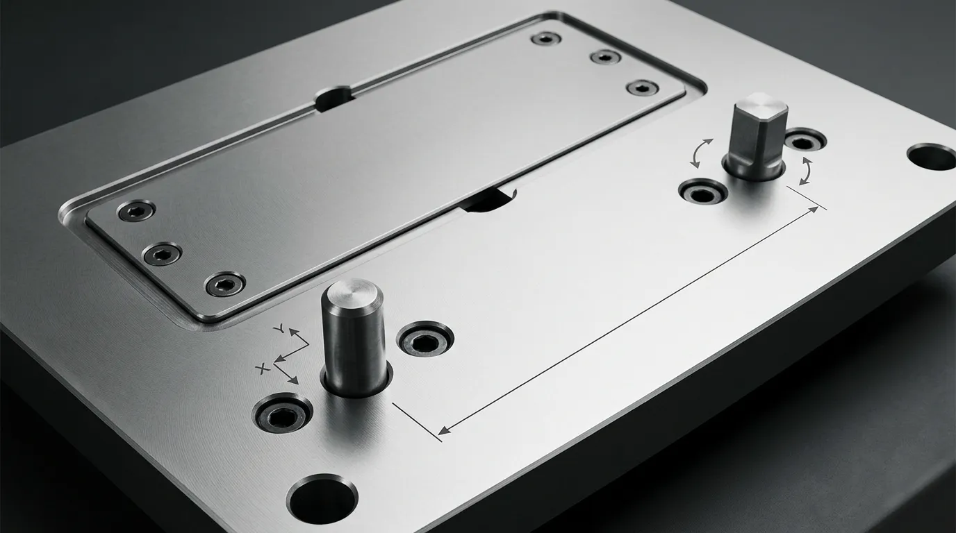
What the Positioning-Pin Layout Must Control
Before placing any pin, define what the component is allowed to do.
A plate or insert resting on a mating surface can still move in three ways within that plane:
- translate along the X direction;
- translate along the Y direction;
- rotate around an axis perpendicular to the plate.
The positioning-pin layout must control those three in-plane movements. The mating face establishes the seating plane, while screws or clamps retain the component against that face.
This distinction matters because not every mold component performs the same task.
Separate Locating, Guiding, Fastening, and Load Control
| Feature | Primary role | What it should not be assumed to do |
|---|---|---|
| Positioning or dowel pin | Establish repeatable plate or insert location | Replace all clamping or carry every operating load |
| Guide pin and bushing | Guide mold halves during opening and closing | Provide the only fixed location for a removable insert |
| Mounting screw | Clamp or retain the component | Establish precise, repeatable position by itself |
| Side lock or interlock | Supplement final positioning or resist particular lateral conditions | Replace a properly defined plate-locating scheme in every application |
A fixed dowel location and a moving guide system may both contribute to alignment, but they solve different problems. Detailed guide-system selection, wear, and maintenance belong with mold guide pins, not in the positioning-pin layout itself.
Positioning pins should also not be treated automatically as the main load-carrying elements. Where the mold experiences significant lateral force, final parting-line location or load resistance may require side locks, taper locks, interlocks, shoulders, or other structural features.
Control Three In-Plane Motions Without Adding Redundant Constraints
The layout should constrain only the movements that must be controlled.
A common approach is:
- A primary round locator controls translation in X and Y.
- A secondary locator prevents rotation.
- The mating surface controls seating.
- Screws provide clamping or retention.
Adding more tightly fitted pins does not necessarily increase accuracy. If several locators attempt to control the same movement, small differences in hole position, pin size, temperature, or machining error can make the component difficult to assemble.
This condition is called overconstraint. Its effects may include binding, forced assembly, internal stress, damaged locating holes, or inconsistent seating.
Choose the Primary and Secondary Locating Scheme
The primary and secondary locators should be selected according to the movement each feature must control.
The correct arrangement depends on component geometry, manufacturing tolerances, operating temperature, assembly frequency, and the distance between locating points. No one arrangement is best for every mold.
Use the Primary Round Pin to Establish the Main Location
The primary round pin normally establishes the main in-plane position. Its cylindrical contact controls movement in two directions.
Place this locator relative to the functional mold feature rather than choosing a location only because it is near a convenient plate corner. For example, if the position of a cavity insert relative to another machined feature is critical, the primary locator should belong to the same functional datum strategy.
The primary location should also be accessible for:
- drilling and reaming;
- dimensional inspection;
- assembly;
- extraction or replacement;
- repair if the hole becomes worn or damaged.
The physical centre of the plate is not automatically the best primary location. Functional control matters more than visual symmetry.
Relieve the Secondary Direction When Two Tight Round Locations Would Bind
A second locator is required to prevent the component from rotating around the primary pin. The problem is that a second tightly fitted round pin also tries to control X and Y.
If the centre distance between the two holes differs slightly from the centre distance between the two pins, the assembly can bind even when each individual diameter is within tolerance.
A diamond pin, relieved pin, or pin-and-slot arrangement avoids this redundant constraint. The secondary locator contacts the mating feature in the direction required to prevent rotation while allowing clearance in the perpendicular direction.
The relief must be oriented correctly. If the relieved direction is turned the wrong way, the secondary locator may fail to control rotation or may still create the centre-distance conflict it was intended to solve.
ASME Y14.5 provides the formal framework for communicating datum relationships and controlled degrees of freedom. Technical guidance from FARO on diamond-pin location also illustrates how directional relief reduces redundant constraint.
| Locating arrangement | Constraint behaviour | Main advantage | Main limitation |
| Two closely fitted round pins | Both pins attempt to control two directions | Simple geometry | Sensitive to centre-distance error and thermal variation |
| Round pin plus diamond or relieved pin | Primary controls X/Y; secondary controls rotation | Reduces overconstraint | Relief orientation must be defined correctly |
| Round pin plus slotted secondary hole | Slot permits movement in one direction | Easy to understand and inspect | Slot manufacture and contact geometry must be controlled |
| Round pin plus floating locator | Secondary feature compensates for larger variation | Useful where centre distance changes significantly | More complex component and inspection requirements |
A floating locator may be useful where centre-distance change is larger than a simple relieved pin can accommodate, such as in long assemblies or components exposed to meaningful temperature differences. It should be selected from verified component data rather than treated as a default solution.
When Two Round Pins May Still Be Appropriate
Two round pins are not automatically wrong.
They may work when:
- the pin centre distance is tightly controlled;
- the mating-hole centre distance is controlled from the same datum system;
- one mating condition includes sufficient clearance;
- temperature variation is limited or accounted for;
- the worst-case tolerance condition has been checked;
- the assembly can be installed without forcing.
The decision must be based on the complete tolerance relationship, not nominal dimensions alone.
Set Useful Pin Spacing and Prevent Reversed Assembly
Positioning pins should generally have the longest practical locator baseline.
The locator baseline is the effective distance between the two locating points that resists rotation. Increasing that distance reduces the angular effect of the same amount of hole-position error.
This does not mean the pins should always be placed at the farthest possible corners. Wider spacing is useful only when the resulting locations remain structurally sound, manufacturable, accessible, and clear of other mold systems.
Use the Longest Practical Locator Baseline
Consider two locating points separated by a short distance. If the secondary hole shifts slightly, the component rotates around the primary locator.
Now consider the same hole-position shift with the locating points farther apart. The resulting angular change is smaller because the error acts across a longer baseline.
The effect becomes more noticeable at functional features located far from the locators. A small angular error near the pins may produce a much larger positional shift at the opposite end of a long insert or plate.
Practical dowel-placement guidance from MISUMI TechCentral follows the same principle: greater separation between locating points reduces sensitivity to equivalent location error. The exact spacing still depends on the mold design.
Balance Wider Spacing Against Plate and System Constraints
Useful separation must be balanced against other requirements.
Check whether a wider pin pattern creates any of the following problems:
- insufficient material between the locating hole and a plate edge;
- intersection with a cooling channel or cooling plug;
- conflict with mounting screws or counterbores;
- interference with ejector pins, return pins, or ejector-plate features;
- conflict with support pillars or load-bearing areas;
- entry into hot-runner manifold, heater, nozzle, or wiring zones;
- blocked sensor or connector access;
- difficult drilling, reaming, or inspection;
- limited extraction access;
- excessive thermal centre-distance change.
A locator placed near a plate edge may improve the angular baseline, but the remaining plate ligament must still withstand manufacturing, assembly, and operating conditions. There is no universal edge distance that is safe for every material, plate thickness, pin diameter, or load case.
Make the Pattern Asymmetric for Mistake-Proof Assembly
A symmetric two-pin pattern may allow a plate or insert to be rotated or reversed and still appear to fit.
An asymmetric pattern makes the intended orientation unique. This can be achieved by:
- offsetting one locator from the centreline;
- using different distances from adjacent edges;
- staggering the primary and secondary locations;
- combining different locator forms;
- making one orientation physically impossible.
The purpose is not visual variety. It is mistake-proofing.
The pattern should remain unambiguous after the mold has been disassembled for maintenance. A technician should not need to rely on memory or a temporary marking to identify the correct orientation.
Check the Layout Against Mold Geometry and Service Access
After choosing the locating scheme and approximate spacing, review the complete mold assembly in CAD.
A locating hole is not an isolated feature. Its drilling path, counterbore, mating hole, extraction path, and surrounding plate material may pass through several stacked components.
Create a Mold-System Obstacle Map Before Drilling Any Locator Hole
Show all relevant systems in the same review model:
- cooling channels, plugs, fittings, and cross-drillings;
- mounting screws and counterbores;
- ejector-pin and return-pin holes;
- ejector-plate movement envelopes;
- support pillars;
- hot-runner manifolds, nozzles, heaters, and wiring;
- slide and lifter mechanisms;
- sensors and connectors;
- lifting holes and handling features;
- insert pockets and neighbouring replaceable components.
Check hidden paths, not only visible bodies. A proposed locating hole may clear a component in one plate but intersect a cooling drilling or screw counterbore deeper in the stack.
Movement also matters. A hole that is clear in the closed CAD position may conflict with an ejector, slide, or other moving feature during operation or maintenance.
Preserve Plate Strength and Access for Assembly, Inspection, and Removal
A workable layout must remain serviceable throughout the mold’s life.
Confirm that:
- the hole can be drilled and reamed from the intended direction;
- inspection equipment can access the locating surfaces or datums;
- the pin has an extraction method when replacement may be required;
- plate separation does not trap the pin unexpectedly;
- the insert can be removed without damaging the locating surfaces;
- the selected engagement length does not obstruct neighbouring features;
- future hole repair, bushing, or oversize rework remains possible.
A precise location that cannot be machined, measured, or repaired is not a complete design.
Define Functional Datums, Position Tolerances, and Thermal Relief
The locating pattern must be communicated through a drawing or controlled digital model that reflects the intended function.
Pin diameter alone is not enough. The drawing must also control where the holes are located relative to the component’s functional datums.
Dimension the Locator Pattern From Functional Datums
Select datums according to how the mold plate or insert works in the assembly.
A practical datum strategy should identify:
- the seating surface;
- the primary functional reference;
- the direction that establishes orientation;
- the relationship between the primary and secondary locating holes;
- the critical molded, machined, or mating feature controlled by the layout.
Avoid locating both holes only from arbitrary outside edges unless those edges genuinely control mold function.
Positional tolerancing can communicate the permissible location of the hole axes relative to the datum reference frame. The inspection method should reproduce the same datum setup used by the design.
The article does not prescribe one tolerance value because the correct value depends on the required repeatability, component size, manufacturing process, inspection capability, and mating clearances.
Validate the Worst-Case Fit and Temperature Condition
Check the assembly at the most restrictive combination of permissible dimensions.
The analysis may need to include:
- maximum pin diameter;
- minimum mating-hole diameter;
- position error of the installed pins;
- position error of the mating holes;
- form and perpendicularity variation;
- temperature-related change in pin or hole centre distance;
- orientation and available relief at the secondary locator.
The ISO 286 limits-and-fits system provides standard terminology and tolerance classes for mating holes and shafts. Parallel dowel-pin categories may also be specified using standards such as ISO 8734 or ISO 2338 where applicable.
These standards provide a framework. They do not select the correct fit for a particular mold automatically.
Thermal movement deserves attention when:
- the locator baseline is long;
- the mating components use different materials;
- assembly and operating temperatures differ;
- one component heats more than the other;
- the mold operates across a wide temperature range.
A relieved secondary direction can accommodate permitted centre-distance change while maintaining rotational control. The relief must still leave enough contact in the controlled direction to meet the location requirement.
Review Common Layout Failures Before Releasing the Drawing
Most positioning-pin problems can be traced to a small set of layout mistakes.
| Layout mistake | Likely consequence | Corrective direction |
| Too many tight locating pins | Binding or forced assembly | Remove redundant constraints or introduce directional relief |
| Two round pins with incompatible centre distances | Difficult assembly or damaged holes | Review fit, position tolerance, and secondary-locator design |
| Locators placed too close together | Increased angular sensitivity | Increase the useful baseline where practical |
| Symmetric pattern | Reversed plate or insert assembly | Stagger or offset one locator |
| Pins located from arbitrary plate edges | Functional feature misalignment | Dimension from functional datums |
| Diamond pin oriented incorrectly | Lost rotational control or continued binding | Define the controlled and relieved directions on the drawing |
| Hole too near an edge or pocket | Weak plate ligament or cracking risk | Reposition or verify the remaining section analytically |
| Hidden collision with cooling or ejection features | Machining rework or system damage | Run a full-depth CAD interference review |
| No extraction access | Difficult maintenance or destructive removal | Add a removal path or extraction feature |
| Nominal-only tolerance check | Assembly failure at tolerance limits | Validate the worst-case condition |
| Guide pins or screws treated as final fixed locators | Inconsistent insert or plate position | Assign each feature a separate defined function |
| Copied spacing rule | Unverified design | Base placement on geometry, loading, tolerances, and access |
Pre-Release Layout Checklist
Before releasing the mold positioning pin layout design, confirm the following:
- The functional seating surface and datums are defined.
- The required X, Y, and rotational constraints are identified.
- The primary locator establishes the intended main position.
- The secondary locator controls rotation in the correct direction.
- Redundant directional constraint has been removed where necessary.
- The locator baseline is as long as practical.
- The pattern cannot be assembled in the wrong orientation.
- Plate-edge and pocket ligaments remain acceptable.
- Cooling, ejection, fastening, support, hot-runner, sensor, and wiring conflicts have been checked.
- Drilling, reaming, inspection, assembly, and extraction access are available.
- Worst-case pin size, hole size, position, and temperature have been reviewed.
- Drawing notes identify locator function, datums, controlled direction, fits, and applicable standards.
- Screws, guide pins, and interlocks have clearly separated roles.
Prepare the Pin Specification and Supplier Handoff
Once the layout has been validated, convert the design into a complete component and hole specification.
Do not send only a nominal pin diameter and overall length. The supplier needs enough information to understand how the component functions in the locating system.
Include the Functional and Inspection Requirements on the Drawing
Depending on the design, specify:
- whether the component is the primary or secondary locator;
- whether it is round, diamond, relieved, tapered, shouldered, or otherwise modified;
- the controlled and relieved directions;
- nominal diameters and lengths;
- mounting and locating portions;
- lead-in geometry;
- removal or extraction features;
- applicable material and heat-treatment requirements;
- surface-finish or treatment requirements where necessary;
- datum references and positional controls;
- mating-hole requirements;
- inspection characteristics and required records;
- applicable ISO or drawing standards;
- drawing revision and quantity.
The mounting fit and the locating fit should be treated as separate functional decisions. One portion may retain the pin in a plate, while another portion locates the mating component. The exact fit must be validated from the application, tolerance analysis, and qualified manufacturing data.
Decide Between a Standard and Custom Locating Component
A standard component is usually preferable when its geometry, tolerance, material, removal method, and available lengths meet the design.
Custom geometry may be justified when the layout requires:
- a special relieved direction;
- a nonstandard shoulder;
- a tapered locating portion;
- an extraction thread;
- an unusual engagement length;
- restricted installation access;
- a special interface between mounting and locating diameters.
Sunshine lists straight, tapered, and drawing-based custom options on its dowel-pin product page. Its website also presents customization of dimensions, tolerance, material, and surface finish. These are listed offerings rather than proof that every drawing or tolerance can be produced, so project-specific capability should be confirmed before release.
For broader guidance on deciding between catalogue components and customized parts, see mold standard parts.
After the locator roles, dimensions, datums, tolerances, material requirements, operating conditions, and inspection needs are defined, the drawing can be reviewed with a component supplier. Sunshine’s contact page provides a route for discussing standard or custom locating-pin requirements without replacing the mold designer’s own fit, strength, and tolerance validation.
Share:


Written By Tonmoy
NEWS
GET SERVICE
With quality parts to meet every budget and friendly staff trained to make your visit informative and hassle free.
